Cisco IOS VRF-Lite
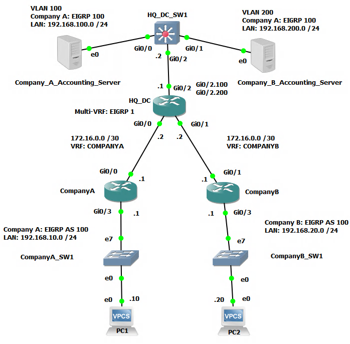
Network Topology
Difference Between VRF and VRF-Lite Explained
VRF (Virtual Routing and Forwarding) and VRF-Lite (also known as Multi-VRF CE or MVPN) are both technologies used in networking to create multiple virtual routing and forwarding instances within a single physical router.
The main difference between the two is in the scope of their implementation. VRF is typically used in service provider networks, where it allows for multiple customers to share the same physical infrastructure while still maintaining separate and isolated routing domains. VRF-Lite, on the other hand, is typically used in enterprise networks, where it allows for multiple logical networks to be created within a single physical network infrastructure.
In summary, VRF is used for service provider networks, and VRF-Lite is used for enterprise networks.
Scenario
Company A has just completed an M&A process and acquired Company B. As part of the post acquisition integration process the decision was made to move Company B's IT equipment into the datacenter hosting facility used by Company A. However, there are some critical elements in Company B such as network addressing and routing that cannot be immediately changed and must stay in place. It is a must, at least in the near to medium term to keep the Company B Accounting and Finance systems separate and secured from other parts of the overall company network while still providing the necessary access to authorized users and their computers. Additionally it was discovered that Company B uses the same network subnet as Company B for the uplink to the Company B main router. This has further complicated the plan to consolidate the topology to just one main router (HQ_DC). However, you have a plan to use VRF-Lite and some VLAN architecture to solve these challenges.
Configuration
These configuration steps will demonstrate the configuration for both Company A and Company B for completeness. Obviously in the scenario much of Company A's infrastructure configuration would already be done.
CompanyA Router
CompanyA>enable
CompanyA#configure terminal
CompanyA(config)#interface gigabitEthernet 0/3
CompanyA(config-if)#ip address 192.168.10.1 255.255.255.0
CompanyA(config-if)#no shutdown
CompanyA(config-if)#interface gigabitEthernet 0/0
CompanyA(config-if)#ip address 172.16.0.1 255.255.255.252
CompanyA(config-if)#no shutdown
CompanyA(config-if)#exit
CompanyA(config)#router eigrp 100
CompanyA(config-router)#network 0.0.0.0 0.0.0.0
CompanyA(config-router)#no auto-summary
CompanyA(config-router)#end
CompanyB Router
CompanyB>enable
CompanyB#configure terminal
CompanyA(config)#interface gigabitEthernet 0/3
CompanyA(config-if)#ip address 192.168.20.1 255.255.255.0
CompanyA(config-if)#no shutdown
CompanyA(config-if)#interface gigabitEthernet 0/0
CompanyA(config-if)#ip address 172.16.0.1 255.255.255.252
CompanyA(config-if)#no shutdown
CompanyA(config-if)#exit
CompanyA(config)#router eigrp 100
CompanyA(config-router)#network 0.0.0.0 0.0.0.0
CompanyA(config-router)#no auto-summary
CompanyA(config-router)#end
HQ_DC Router
HQ_DC>enable
HQ_DC#configure terminal
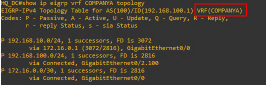
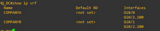
HQ_DC(config)#ip vrf COMPANYA
HQ_DC(config-vrf)#exit
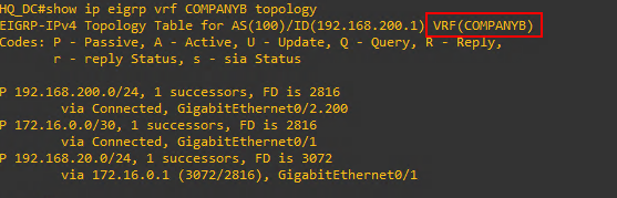
HQ_DC(config)#ip vrf COMPANYB
HQ_DC(config-vrf)#exit
HQ_DC(config)#interface gigabitEthernet 0/0
HQ_DC(config-if)#ip address 172.16.0.2 255.255.255.252
HQ_DC(config-if)#description COMPANYA main circuit
HQ_DC(config-if)#ip vrf forwarding COMPANYA
HQ_DC(config-if)#exit
HQ_DC(config)#interface gigabitEthernet 0/1
HQ_DC(config-if)#ip address 172.16.0.2 255.255.255.252
HQ_DC(config-if)#description COMPANYB main circuit
HQ_DC(config-if)#ip vrf forwarding COMPANYB
HQ_DC(config-if)#exit
HQ_DC(config)#interface gigabitEthernet 0/2
HQ_DC(config-if)#no shutdown
HQ_DC(config-if)#interface gigabitEthernet 0/2.100
HQ_DC(config-subif)#description COMPANYA dc circuit
HQ_DC(config-subif)#encapsulation dot1q 100
HQ_DC(config-subif)#ip vrf forwarding COMPANYA
HQ_DC(config-subif)#ip address 192.168.100.1 255.255.255.0
HQ_DC(config-if)#interface gigabitEthernet 0/2.200
HQ_DC(config-subif)#description COMPANYB dc circuit
HQ_DC(config-subif)#encapsulation dot1q 200
HQ_DC(config-subif)#ip vrf forwarding COMPANYB
HQ_DC(config-subif)#ip address 192.168.200.1 255.255.255.0
HQ_DC(config-subif)#exit
HQ_DC(config)#router eigrp 1
HQ_DC(config-router)#address-family ipv4 vrf COMPANYA
HQ_DC(config-router-af)#network 0.0.0.0 0.0.0.0
HQ_DC(config-router-af)#autonomous-system 100
HQ_DC(config-router-af)#no auto-summary
HQ_DC(config-router-af)#exit
HQ_DC(config-router)#address-family ipv4 vrf COMPANYB
HQ_DC(config-router-af)#network 0.0.0.0 0.0.0.0
HQ_DC(config-router-af)#autonomous-system 100
HQ_DC(config-router-af)#no auto-summary
HQ_DC_SW1 Switch
HQ_DC_SW1>enable
HQ_DC_SW1#configure terminal
HQ_DC_SW1(config)#vlan 100
HQ_DC_SW1(config-vlan)#name COMPANYA
HQ_DC_SW1)config-vlan)#exit
HQ_DC_SW1(config)#vlan 200
HQ_DC_SW1(config-vlan)#name COMPANYB
HQ_DC_SW1)config-vlan)#exit
HQ_DC_SW1(config)#interface gigabitEthernet 0/2
HQ_DC_SW1(config-if)#switchport trunk encapsulation dot1q
HQ_DC_SW1(config-if)#switchport mode trunk
HQ_DC_SW1(config-if)#switchport trunk allowed vlan 100,200
HQ_DC_SW1(config-if)#interface gigabitEthernet 0/0
HQ_DC_SW1(config-if)#switchport access vlan 100
HQ_DC_SW1(config-if)#interface gigabitEthernet 0/1
HQ_DC_SW1(config-if)#switchport access vlan 200
HQ_DC_SW1(config-if)#exit
HQ_DC_SW1(config)#interface vlan 100
HQ_DC_SW1(config-if)#ip address 192.168.100.2 255.255.255.0
HQ_DC_SW1(config-if)#exit
HQ_DC_SW1(config)#interface vlan 200
HQ_DC_SW1(config-if)#ip address 192.168.200.2 255.255.255.0
PCs and Servers
PC1>ip 192.168.10.10/24 192.168.10.1
PC2>ip 192.168.20.20/24 192.168.20.1
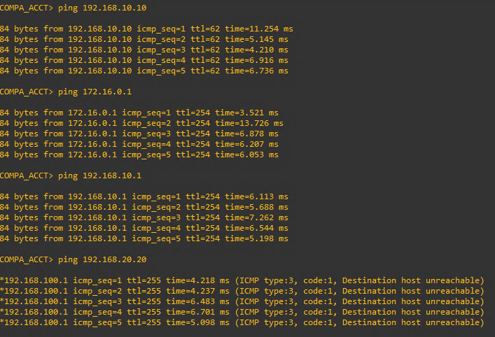
COMPA_ACCT> ip address 192.168.100.10/24 192.168.100.1
COMPB_ACCT> ip address 192.168.200.20/24 192.168.200.1
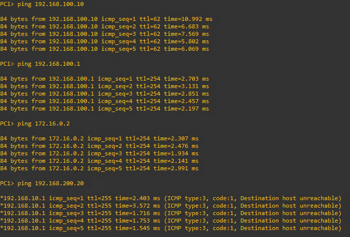
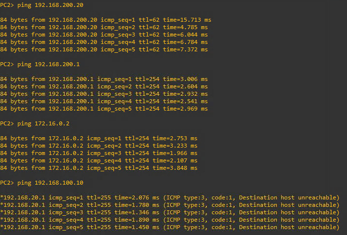
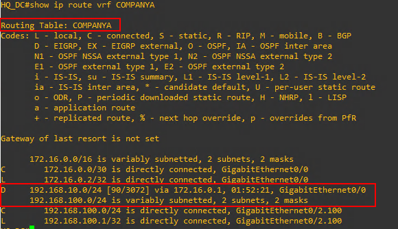
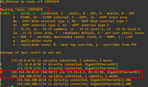
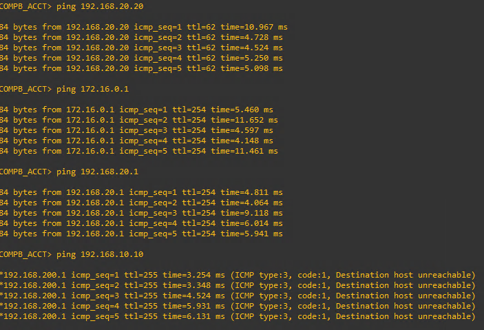
Test and Verify Connectivity and Configuration