Cisco ASA 5505 Internet Access
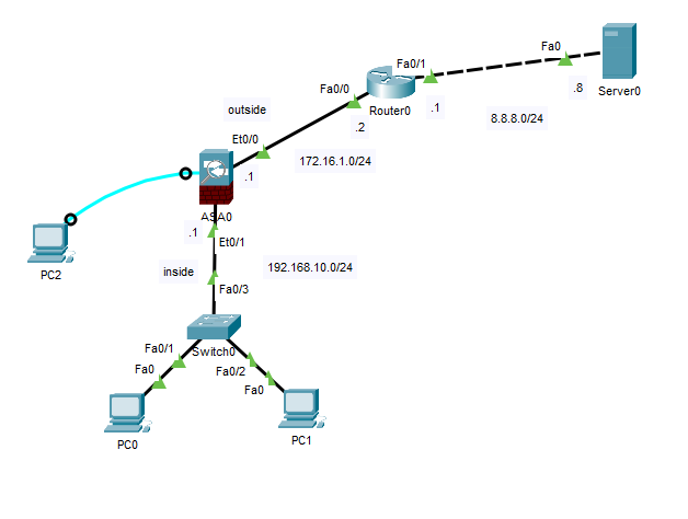
Network Topology
Step 1 - Remove Existing ASA Configuration
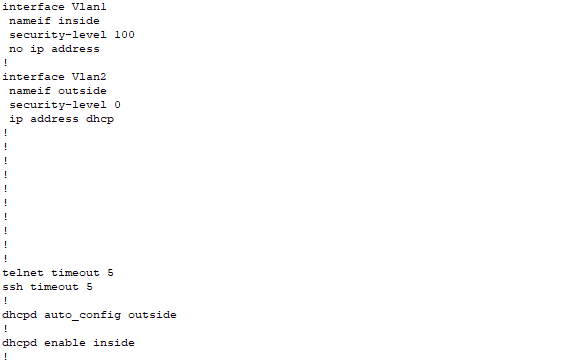
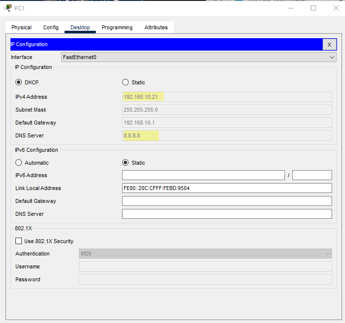
In Cisco Packet Tracer the ASA 5505 already starts out with some configuration as show by the show running-config command output below.
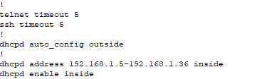
It also has a dhcpd server enabled and partially configured.
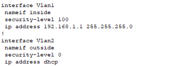
In addition, there are configure vlan interfaces with assigned interfaces.
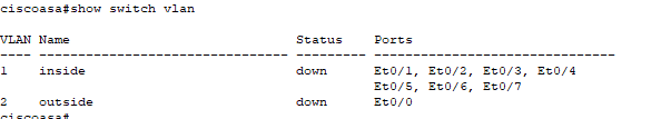
To create our own configuration, we will have to first dismantle the configuration elements that already are in place.
ciscoasa>enable
password:
ciscoasa#configure terminal
ciscoasa(config)#hostname ASA0
ASA0(config)#interface vlan 1
ASA0(config-if)#no ip address
ASA0(config-if)#exit
ASA0(config)#no dhcpd address 192.168.1.5-192.168.1.36 inside
ASA0(config)#end
ASA0#show running-config
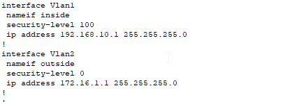
Step 2 - Configure VLAN Interfaces, Assign Ethernet Interfaces to Correct VLANs, and Ensure Correct Security-Levels
ASA0#configure terminal
ASA0(config)#interface vlan 1
ASA0(config-if)#ip address 192.168.10.1 255.255.255.0
ASA0(config-if)#nameif inside
ASA0(config-if)#security-level 100
ASA0(config-if)#no shutdown
ASA0(config-if)#exit
ASA0(config)#interface vlan 2
ASA0(config-if)#ip address 172.16.1.1 255.255.255.0
ASA0(config-if)#nameif outside
ASA0(config-if)#security-level 0
ASA0(config-if)#no shutdown
ASA0(config-if)#exit
ASA0(config)#interface ethernet 0/1
ASA0(config-if)#switchport access vlan 1
ASA0(config-if)#exit
ASA0(config)#interface ethernet 0/0
ASA0(config-if)#switchport access vlan 2
ASA0(config-if)#end
ASA#show running-config
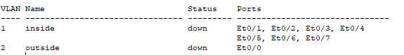
ASA#show switch vlan
Step 3 - Configure the ISP Router
Now it's time to configure the router. This router (Router0) is like the ISP router on the far side of our connection to the Internet. In this configuration I will be using OSPF to dynamically route the networks of 172.16.1.0/24 and 8.8.8.0/24. You could just as easily use static routes and default gateways or even another dynamic routing protocol. I just chose OSPF.
Router0>enable
Router0#configure terminal
Router0(config)#interface fastEthernet 0/0
Router(config-if)#ip address 172.16.1.2 255.255.255.0
Router(config-if)#no shutdown
Router(config-if)#interface fasEthernet 0/1
Router(config-if)#ip address 8.8.8.1 255.255.255.0
Router0(config-if)#exit
Router0(config)#router ospf 1
Router0(config-router)#network 172.16.1.0 0.0.0.255 area 0
Router0(config-router)#network 8.8.8.0 0.0.0.255 area 0
Router0(config-router)#end
Router0#
Step 4 - Configure DHCP Server on ASA
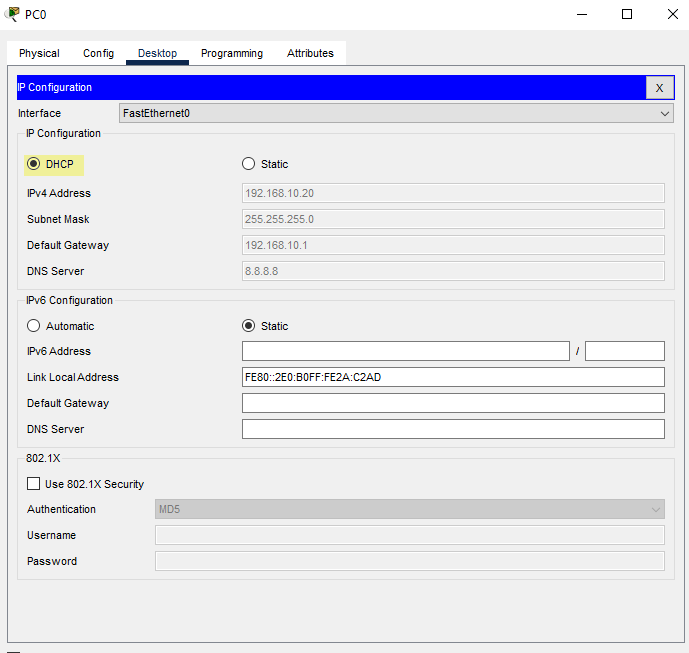
Next let's configure the dhcp server addressing on the ASA0 firewall. The dhcpd is already enabled we just have to configure the correct addressing to match our internal LAN subnet addressing. Before we configure the ASA through, make sure the PC0 and PC1 are set to obtain their IP addresses via DHCP.
ASA0#configure terminal
ASA0(config)#dhcpd address 192.168.10.20-192.168.10.30 inside
ASA0(config)#dhcpd dns 8.8.8.8 interface inside
ASA0(config)#end
ASA0#show running-config
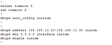
Check PC0 and PC1 IP addresses
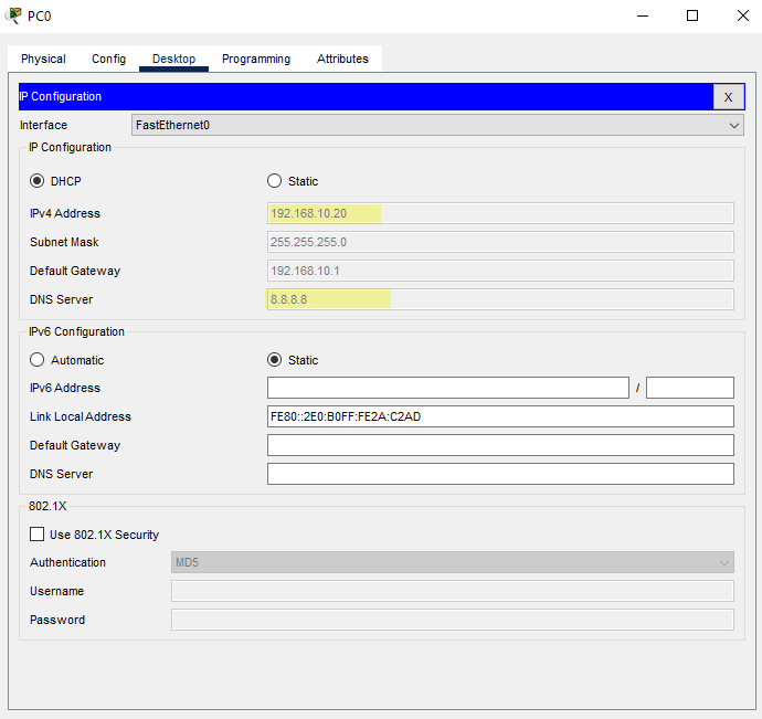
DHCP is working properly.
Step 5 - Configure Default Route on ASA, Create Network Object, and Configure Network Address Translation (NAT)
ASA0#configure terminal
ASA0(config)#route outside 0.0.0.0 0.0.0.0 172.16.1.2
ASA0(config)#object network LAN
ASA0(config-network-object)#subnet 192.168.10.0 255.255.255.0
ASA0(config-network-object)#nat (inside,outside) dynamic interface
ASA0(config-network-object)#exit
ASA0(config)#access-list in_to_internet extended permit tcp any any
ASA0(config)#access-list in_to_internet extended permit icmp any any
ASA0(config)#access-group in_to_internet in interface outside
ASA0(config)#
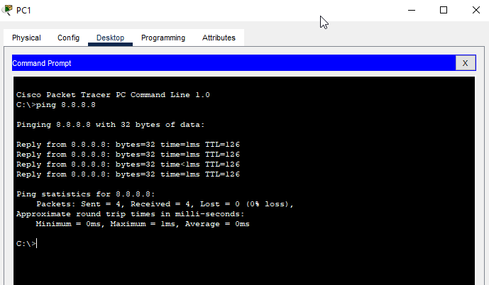
Now check ping to the server at 8.8.8.8 from PC0 or PC1
Now we will verity NAT
ASA0#show xlate

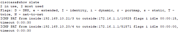
Nothing to show so start a continuous ping from PC0 and PC1 ping -t 8.8.8.8 and re-run the show xlate command on the ASA
ASA0#show xlate
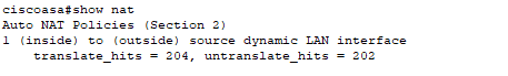
ASA0#show nat