
OSPF Open Shortest Path First Protocol
- Most widely used interior gateway routing protocol
- Open standard (non-proprietary)
- Fast convergence
- It's been around since 1989.
How does it differ from other routing protocols?
Distance Vector ProtocolsDistance Vector routing protocols base their decisions on the best path to a given destination based on the distance. If the distance metric is hop, then each time a packet goes through a router, a hop is considered to have traversed. The route with the least number of hops to a given network is concluded to be the best route towards that network. The vector shows the direction to that specific network. Distance vector protocols send their entire routing table to directly connected neighbors. |
Link State ProtocolsLink state protocols are also called shortest-path-first protocols. Link state routing protocols have a complete picture of the network topology. Hence they know more about the whole network than any distance vector protocol. Three separate tables are created on each link state routing enabled router. One table is used to hold details about directly connected neighbors, one is used to hold the topology of the entire internetwork and the last one is used to hold the actual routing table. Link state protocols send information about directly connected links to all the routers in the network. |
| RIP and IGRP | OSPF and IS-IS (EIGRP is considered a hybrid protocol because it uses both distance vector and link state.) |
| Only communicates with neighbor routers | Communicates with all other routers in an area |
| Calculates path based on distance and vector | Calculates shortest path based on link-state parameters |
| Passes entire routing table to directly connected neighbor routers | Passes link-state routing updates to other routers |
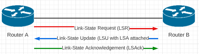
Link-State Routing
1. LSRRouter A send a link-state request (LSR) to gather route information from the neighbor router -- Router B |
2. LSURouter B replies with a Link -State Update (LSU) containing the requested Link-State Advertisement (LSA) information. |
3. LSAckRouter A receives the LSU with LSA attached and sends a Link-State Acknowledgement (LSAck) back to Router B |
Dijkstra's Algorithm
The speed of OSPF can be attributed to the Dijkstra Algorithm (Shortest Path First)
|
|
Illustration of Dijkstra's algorithm finding a path from a start node (lower left, red) to a goal node (upper right, green) in a robot motion planning problem. Open nodes represent the "tentative" set (aka set of "unvisited" nodes). Filled nodes are the visited ones, with color representing the distance: the greener, the closer. Nodes in all the different directions are explored uniformly, appearing more-or-less as a circular wavefront as Dijkstra's algorithm uses a heuristic identically equal to 0. * source: https://en.wikipedia.org/wiki/Dijkstra%27s_algorithm |

OSPF Path Selection
- Link-state information is flooded throughout the network, from router to router within an area, enabling all the routers within the area to have a synchronized and identical map of the network area.
- The Dijkstra's Algorithm (Shortest Path First) is then applied to this map of information to calculate the best (shortest) path.
- Once the Dijkstra Algorithm is applied and discovers the best routes the routes are applied to the routing table in the routers.
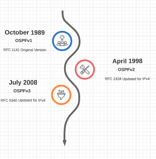
OSFP History
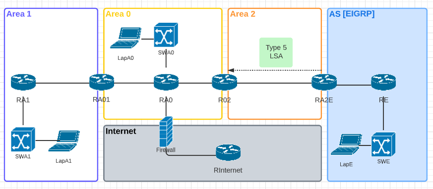
OSPF Areas
An OSPF Area is a network where routers all have the same routing information (LSAs) Network updates are localized per area and routers share topology information within the second table mentioned above (topology table). To reduce the size of the topology table in very large OSPF implementations the areas can be broken up into different OSPF area limits. Thus, the network updates will only be applied to the specifically identified area.
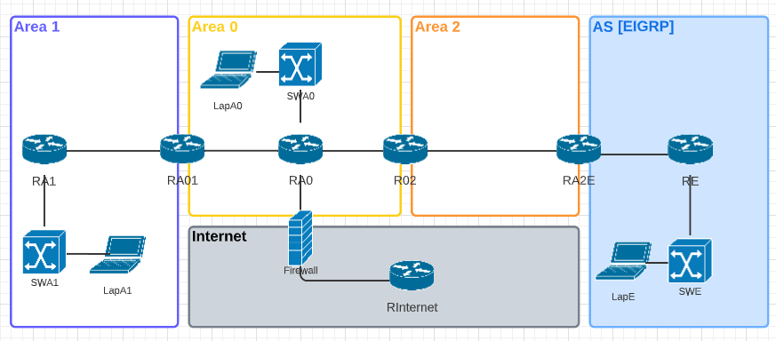
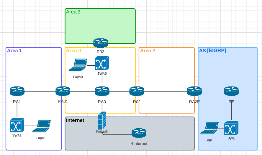
Area 0 is the Backbone and all other areas must connect back to Area 0
Adding an Area3 through Area 1 (as in the diagram below) would not be a correct or allowed configuration as Area 3 is NOT connected to Area 0, the Backbone.
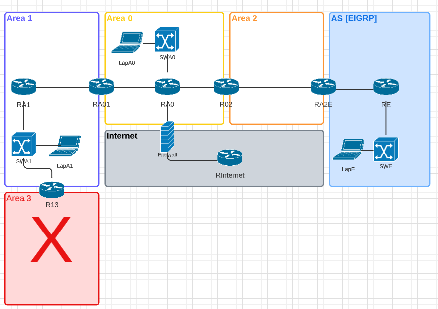
Adding Area 3 by connecting it to the backbone is the correct method for adding another OSPF Area as in the updated diagram below.
OSPF Neighbor Requirements
- Must be on the same Area
- Must match the following fields:
- Hello timer - the interval in seconds that a router sends hello messages out of an OSPF-enabled interface
- Dead timer - the time in seconds that an OSPF enabled interface will wait to receive a hello message from a neighbor before considering that neighbor to be down.
- Authentication
- Maximum transmission unit (MTU)
- Stub flags
- Hello timer - the interval in seconds that a router sends hello messages out of an OSPF-enabled interface
Hello timer Defaults: Sent every 10 seconds on broadcast or P2P networks. Sent every 30 seconds on non-broadcast multiple assess networks (NBMA) (i.e.; Frame Relay). Hello packets are sent to all other routers to the following broadcast addresses depending on IP version
- IPv4 - 224.0.0.5
- IPv6 - FF02::5
When sending Hello packets to designated routers the following addresses are used. What is a designated router? See Below.
- IPv4 - 224.0.0.6
- IPv6 - FF02::6
Dead timer Defaults: 4 times the hello timer.
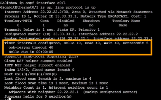
Wait timer is the number of seconds a router waits for the designated router or backup designated router to be advertised before beginning an election.
Retransmit is the number of seconds a router waits before retransmitting an OSPF packet that has not been acknowledged.
How to Change the Various Intervals
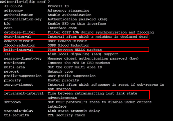
Router0(config)# interface gigabitEthernet 0/1
Router0(Config-if)#ip ospf hello-interval 20
Designated Router (DR) and Backup Designated Router (BDR)
Router adjacencies are neighbor routers that share LSUs and database description packets.
A large network could have a huge number of adjacencies as show by this formula:
[n*(n-1]/2So for 4 routers the number of adjacencies would be [4*(4-1)]/2 = 6. And for 10 the number of adjacencies would be [10*(10-1)]/2 = 45. As you can see the number of adjacencies becomes large very quickly. And a router will not be 'close' to all these adjacencies. Instead, an OSPF router is close to a specific router (neighbor) and that router is deemed the designated router (DR). And they also form an adjacency with a backup designated router (BDR). This is to reduce the adjacency volume.
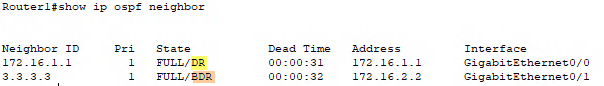
How does a router select its DR and BDR?
- Priority level (default is 1) The higher the priority the better.
- To adjust the priority level go to the interface global config and enter
Router1(config-if)# ip ospf priority [#]
-
- If you do not want a router to be considered as a DR or BDR set the priority level to zero (0) and it will no longer participate in the election.
- Router ID
- Router ID can be configured
Router1(config)#router ospf 1
Router1(config-router)#router-id [id]
- Loopback interface IP address
- Interface IP address
Not all network types conduct a DR/BDR election
| Network Type | DR/BDR Election? |
| Point to Point | No |
| Broadcast | Yes |
| Non broadcast multiple access (NMBA) | Yes |
| Point to Multipoint | No |
Area Border Router (ABR)
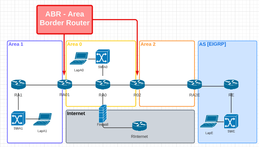
Typically an ABR has more processing power that an non ABR since they will have to store the routing tables for multiple OSPF Areas.
Autonomous System Boundary Router (ASBR)
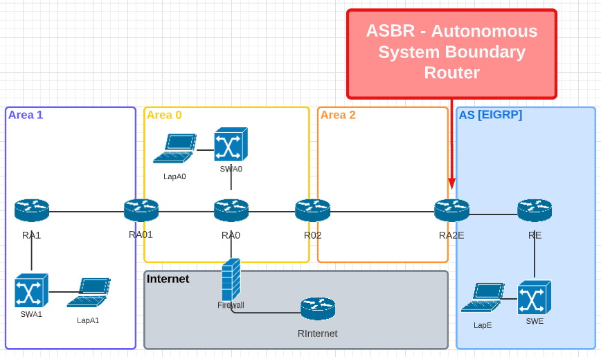
This router has one interface connected to OSPF and another interface with an entirely different routing protocol (i.e.; EIGRP)
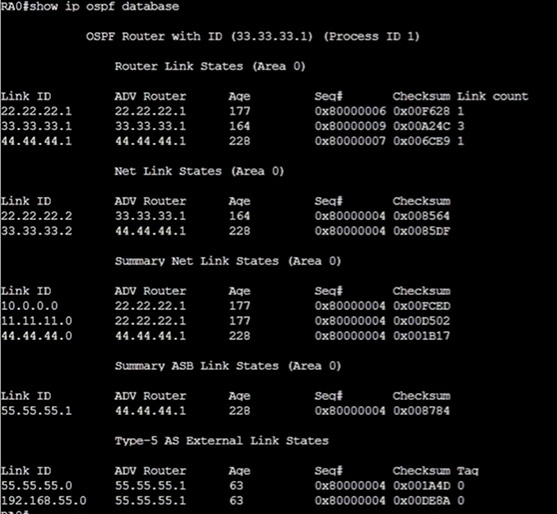
LSA Types
- Type 1: Router LSA - this LAS type is what the routers use to advertise directly attached networks.
- Type 1: Network LSA - used in transit networks for DR/BDR elections
- No need for Type 2 Network LSA in Point to Point (except Frame Relay) or Point to Multipoint
- No need for Type 2 Network LSA of links going to end devices
- Type 3: Summary LSA - these LSAs come into play for Area Border Routers (ABR)
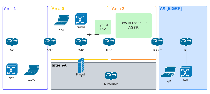
- Type 4 and Type 5 LSAs are created when an OSPF network is connected to another autonomous system (i.e.; EIGRP)
- Type 4: Summary ASBR LSA
- Created by an ABR to tell an Area how to reach and ASBR
-
- Type 5: AS External LSA
- Type 5 is created by the ASBR to advertise networks in different autonomous systems
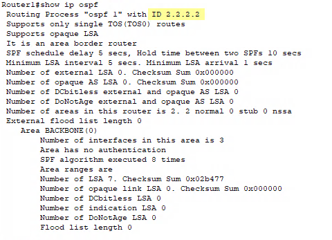
Router0#show ip ospf database
Stub Areas
An area that is only connected to the backbone and is not connected to any other autonomous systems
Route Summarization
| Decimal | Octet 1 | Octet 2 | Octet 3 | Octet 4 |
| 192.168.8.0 | 11000000 | 10101000 | 00001000 | 00000000 |
| 192.168.9.0 | 11000000 | 10101000 | 00001001 | 00000000 |
| 192.168.10.0 | 11000000 | 10101000 | 00001010 | 00000000 |
| 192.168.11.0 | 11000000 | 10101000 | 00001011 | 00000000 |
| SUMMARY IP | 11000000 | 10101000 | 00001000 | 00000000 |
| 192 | 168 | 8 | 0 | |
| Subnet Mask | 11111111 | 11111111 | 11111100 | 00000000 |
| /22 | 255 | 255 | 252 | 0 |
Summarization = 192.168.8.0 with subnet 255.255.252.0 (/22)