Cisco IOS Basic MPLS VPN
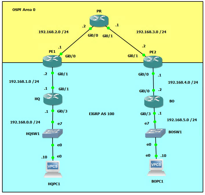
Network Topology
What is MPLS?
Multiprotocol Label Switching (MPLS) is a type of data-carrying technique for high-performance telecommunications networks. It directs data from one network node to the next based on short path labels rather than long network addresses, avoiding complex lookups in a routing table. MPLS can provide better performance, security, and service-level agreements (SLAs) for data traffic. The MPLS protocol is used to create virtual private networks (VPNs) and traffic engineering (TE) networks. It is often used in service provider networks, but can also be used in enterprise networks. MPLS can be used to forward packets using labels, rather than routing them based on their IP addresses. This allows for faster forwarding decisions, because the label can be looked up quickly in a table. MPLS also allows for the creation of virtual links, which can be used to connect different networks together, even if they use different routing protocols.
Multiprotocol Label Switching (MPLS) can be used to create Virtual Private Networks (VPNs). A VPN is a private network that uses a public network (such as the Internet) to connect remote sites or users together. MPLS VPNs use MPLS labels to forward packets between sites, instead of routing them based on their IP addresses. This allows for more efficient and secure communications, as well as the ability to create different virtual networks for different customers or applications.
MPLS VPNs can be configured in different ways, such as:
- MPLS Layer 3 VPNs, which use MPLS to forward packets between sites based on their IP addresses. This allows for the creation of virtual networks that use the same IP addresses as the underlying public network.
- MPLS Layer 2 VPNs, which use MPLS to forward packets between sites based on their MAC addresses. This allows for the creation of virtual networks that use different MAC addresses than the underlying public network.
In both cases, MPLS VPNs use a technique called "VPN label" to identify the different VPNs and forward the packets to the correct destination. MPLS VPNs can also use security features such as encryption, to ensure that the data cannot be intercepted or tampered with while in transit.
MPLS VPNs are widely used by service providers to offer VPN services to their customers. They can also be used in enterprise networks to connect remote sites or branch offices together securely. It's also a good choice for interconnecting multiple sites of a large enterprise as it can provide high performance and better security compared to traditional VPN technologies.
MPLS vs SD-WAN
Multiprotocol Label Switching (MPLS) and Software-Defined WAN (SD-WAN) are both technologies used to connect remote sites or users together, but they have some key differences:
-
MPLS is a type of data-carrying technique that directs data from one network node to the next based on short path labels rather than long network addresses. It is primarily used by service providers to offer VPN services to their customers and can also be used in enterprise networks to connect remote sites or branch offices together.
-
SD-WAN, on the other hand, is a software-based approach to managing WAN connections. It allows for the use of multiple types of connections (such as broadband, cellular, or MPLS) and automatically chooses the best one for each application or user based on factors such as cost, quality, or security. SD-WAN also allows for better visibility and control over network traffic, as well as the ability to easily add or remove sites from the network.
-
MPLS is typically more expensive than SD-WAN, but it offers better security, QoS and SLAs. On the other hand, SD-WAN is more flexible and cost-effective, but it may not provide the same level of security and performance as MPLS.
-
MPLS is a more traditional approach that has been used for more than two decades while SD-WAN is a newer technology that uses software to manage network connections.
-
MPLS is a Layer 3 technology while SD-WAN is a Layer 4-7 technology.
In summary, MPLS is a proven and reliable technology that is well-suited for organizations that require high levels of security and Quality of Service (QoS), while SD-WAN is a cost-effective and flexible option that is well-suited for organizations that need to connect multiple sites or users together in a dynamic way.
Configure the Interface Settings on All Routers and PCs (including Loopback Interfaces on Routers)
HQ>enable
HQ#configure terminal
HQ(config)#interface gigabitEthernet g0/1
HQ(config-if)#ip address 192.168.1.1 255.255.255.0
HQ(config-if)#no shutdown
HQ(config)#interface gigabitEthernet g0/3
HQ(config-if)#ip address 192.168.0.1 255.255.255.0
HQ(config-if)#no shutdown
HQ(config-if)#exit
HQ(config)#interface loopback 0
HQ(config-if)#ip address 1.1.1.1 255.255.255.0
HQ(config-if)#end
PE1>enable
PE1#configure terminal
PE1(config)#interface gigabitEthernet g0/0
PE1(config-if)#ip address 192.168.2.1 255.255.255.0
PE1(config-if)#no shutdown
PE1(config)#interface gigabitEthernet g0/1
PE1(config-if)#ip address 192.168.1.2 255.255.255.0
PE1(config-if)#no shutdown
PE1(config-if)#exit
PE1(config)#interface loopback 0
PE1(config-if)#ip address 2.2.2.2 255.255.255.0
PE1(config-if)#end
PR>enable
PR#configure terminal
PR(config)#interface gigabitEthernet g0/0
PR(config-if)#ip address 192.168.2.2 255.255.255.0
PR(config-if)#no shutdown
PR(config)#interface gigabitEthernet g0/1
PR(config-if)#ip address 192.168.3.1 255.255.255.0
PR(config-if)#no shutdown
PR(config-if)#exit
PR(config)#interface loopback 0
PR(config-if)#ip address 3.3.3.3 255.255.255.0
PR(config-if)#end
PE2>enable
PE2#configure terminal
PE2(config)#interface gigabitEthernet g0/0
PE2(config-if)#ip address 192.168.4.1 255.255.255.0
PE2(config-if)#no shutdown
PE2(config)#interface gigabitEthernet g0/1
PE2(config-if)#ip address 192.168.3.2 255.255.255.0
PE2(config-if)#no shutdown
PE2(config-if)#exit
PE2(config)#interface loopback 0
PE2(config-if)#ip address 4.4.4.4 255.255.255.0
PE2(config-if)#end
BO>enable
BO#configure terminal
BO(config)#interface gigabitEthernet g0/0
BO(config-if)#ip address 192.168.4.2 255.255.255.0
BO(config-if)#no shutdown
BO(config-if)#interface gigabitEthernet g0/3
BO(config-if)#ip address 192.168.5.1 255.255.255.0
BO(config-if)#no shutdown
BO(config-if)#exit
BO(config)#interface loopback 0
BO(config-if)#ip address 5.5.5.5 255.255.255.0
BO(config-if)#end
HQPC1>ip 192.168.0.10/24 192.168.0.1
BOPC1>ip 192.168.5.10/24 192.168.5.1
Setup OSPF Topology for the Provider Edge Routers (PE1 and PE2) and Provider Backbone Router (PR)
PE1>enable
PE1#configure terminal
PE1(config)#router ospf 1
PE1(config-router)#network 192.168.2.0 0.0.0.255 area 0
PE1(config-router)#network 2.2.2.0 0.0.0.255 area 0
PE1(config-router)#passive-interface gigabitEthernet 0/1
PR>enable
PR#configure terminal
PR(config)#router ospf 1
PR(config-router)#network 192.168.2.0 0.0.0.255 area 0
PR(config-router)#network 192.168.3.0 0.0.0.255 area 0
PR(config-router)#network 3.3.3.0 0.0.0.255 area 0
PE2>enable
PE2#configure terminal
PE2(config)#router ospf 1
PE2(config-router)#network 192.168.3.0 0.0.0.255 area 0
PE2(config-router)#network 4.4.4.0 0.0.0.255 area 0
PE2(config-router)#passive-interface gigabitEthernet 0/0
Setup MPLS on the ProvideProvider Router Interfaces DO NOT Include the Interfaces Facing the Customer RouterRouters (HQ and BO) on PE1 and PE2
PE1>enable
PE1#configure terminal
PE1(config)#interface gigabitEthernet 0/0
PE1(config-if)#mpls ip
PR>enable
PR#configure terminal
PR(config)#interface gigabitEthernet 0/0
PR(config-if)#mpls ip
PR(config)#interface gigabitEthernet 0/1
PR(config-if)#mpls ip
PE2>enable
PE2#configure terminal
PE2(config)#interface gigabitEthernet 0/1
PE2(config-if)#mpls ip
*You should see a message on the console about the LDP Neighbor switching to a status of UP.
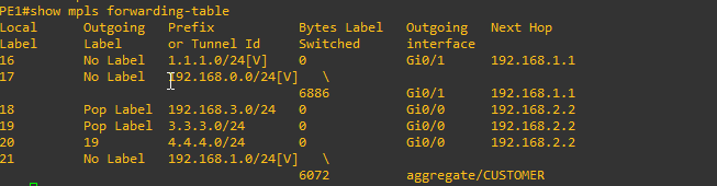
Now let's take a look at the Loopback interfaces by entering the command show mpls forwarding-table.
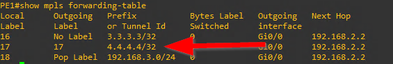
The mask shown on the Loopback interfaces is reporting incorrect so we need to fix this.
PE1(config)#interface loopback 0
PE1(config-if)#ip ospf network point-to-point
PR(config)#interface loopback 0
PR(config-if)#ip ospf network point-to-point
PE2(config)#interface loopback 0
PE2(config-if)#ip ospf network point-to-point
Check the MPLS forwarding-table again to see if the mask is correct on the Loopback
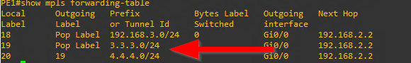
Looks good. the loopback interfaces now have the correct subnet mask of /24
One more thing let's manually force the router-id for mpls to be the Loopback interface IP.
PE1(config)#mpls ldp router-id loopback 0
PR(config)#mpls ldp router-id loopback 0
PE2(config)#mpls ldp router-id loopback 0
Setup Virtual Routing and Forwarding (VRF) for the Customer
PE1>enable
PE1#configure terminal
PE1(config)#ip vrf CUSTOMER
PE1(config-vrf)#rd 100:1
PE1(config-vrf)#route-target both 1:100
PE1(config-vrf)#exit
PE1(config)#interface gigabitEthernet 0/1
PE1(config-if)#ip vrf forwarding CUSTOMER
After setting the vrf on the interface the IP address will be removed and you will have to re-configure it.

PE1(config-if)#ip address 192.168.1.2 255.255.255.0
Now setup the VRF on router PE2 the same way.
PE2>enable
PE2#configure terminal
PE2(config)#ip vrf CUSTOMER
PE2(config-vrf)#rd 100:1
PE2(config-vrf)#route-target both 1:100
PE2(config-vrf)#exit
PE2(config)#interface gigabitEthernet 0/0
PE2(config-if)#ip vrf forwarding CUSTOMER
And don't forget to re-enter the IP configuration for the interface after.
PE2(config-if)ip address 192.168.4.1 255.255.255.0
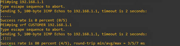
After setting up the VRF you will not be able to ping the interface on the HQ router (192.168.1.1). This is because just using a regular ping without designating the VRF will use the global routing table insteat of the virtual routing table for the CUSTOMER VRF. Instead you have to designate the VRF in the ping command as follows ping vrf CUSTOMER 192.168.1.1
Configure Dynamic Routing Protocols
EIGRP
HQ>enable
HQ#configure terminal
HQ(config)#router eigrp 100
HQ(config-router)#network 192.168.0.0
HQ(config-router)#network 192.168.1.0
HQ(config-router)#network 1.1.1.0
HQ(config-router)#no auto-summary
BO>enable
BO#configure terminal
BO(config)#router eigrp 100
BO(config-router)#network 192.168.4.0
BO(config-router)#network 192.168.5.0
BO(config-router)#network 5.5.5.0
BO(config-router)#no auto-summary
PE1>enable
PE1#configure terminal
PE1(config)#router eigrp1
PE1(config-router)#address-family ipv4 vrf CUSTOMER
PE1(config-router-af)#autonomous-system 100
PE1(config-router-af)#network 192.168.1.0
PE1(config-router-af)#no auto-summary
You should see the EIGRP adjacency message popup

PE2>enable
PE2#configure terminal
PE2(config)#router eigrp1
PE2(config-router)#address-family ipv4 vrf CUSTOMER
PE2(config-router-af)#autonomous-system 100
PE2(config-router-af)#network 192.168.4.0
PE2(config-router-af)#no auto-summary
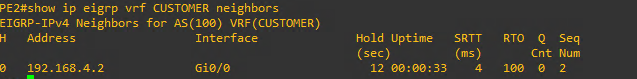
In order to show the EIGRP neighbors from the Provider Edge Routers (PE1 and PE2) keep in mind you have to include the vrf in the command show ip eigrp vrf CUSTOMER neighbors.
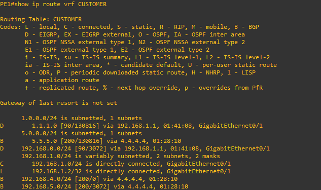
We can also check the routing tables from the Provider routers, but again remember to include the correct VRF designation. show ip route vrf CUSTOMER
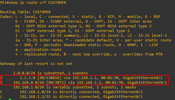
As can be seen above the PE1 Provide Edge Router has learned about the Loopback interface IP of the HQ router as well as the LAN network of 192.168.0.0 And notice that I can ping HQPC1 from the gigabitEthernet 0/1 interface of PE1 but not gigabitEthernet 0/0
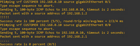
This is as expected because the 0/1 interface is participating in the VRF and knows about the virtual routing table pointing to HQ while the 0/0 interface is not part of the VRF.
iBGP (Internal)
PE1>enable
PE1#configure terminal
PE1(config)#router bgp 1
PE1(config-router)#neighbor 4.4.4.4 remote-as 1
PE1(config-router)#neighbor 4.4.4.4 update-source loopback 0
PE2>enable
PE2#configure terminal
PE2(config)#router bgp 1
PE2(config-router)#neighbor 2.2.2.2 remote-as 1
PE2(config-router)#neighbor 2.2.2.2 update-source loopback 0
You should see the BGP neighbor messages on PE1 and PE2 like below.


Now that we have BGP routing configured we still need to configure the address family and ensure that we are sending communities. In Cisco BGP (Border Gateway Protocol) configuration, the "send-community" command is used to configure the sending of community attributes to other BGP peers. Community attributes are used to group routes together and apply a common set of policies to them. The "send-community" command can be used to specify whether or not to send the standard, extended, or both types of community attributes to BGP peers. The command can also be used to specify whether or not to send the community attributes in both the outbound and inbound directions.
PE1(config)#router bgp 1
PE1(config-router)#address-family vpnv4
PE1(config-router-af)#neighbor 4.4.4.4 activate
PE1(config-router-af)#neighbor 4.4.4.4 send-community both
PE2(config)#router bgp 1
PE2(config-router)#address-family vpnv4
PE2(config-router-af)#neighbor 2.2.2.2 activate
PE2(config-router-af)#neighbor 2.2.2.2 send-community both
Redistribute Protocols
BGP into EIGRP
PE1#configure terminal
PE1(config)#router eigrp 1
PE1(config-router)#address-family ipv4 vrf CUSTOMER
PE1(config-router-af)#redistribute bgp 1 metric 1500 4000 200 10 1500
PE2#configure terminal
PE2(config)#router eigrp 1
PE2(config-router)#address-family ipv4 vrf CUSTOMER
PE2(config-router-af)#redistribute bgp 1 metric 1500 4000 200 10 1500
EIGRP into BGP
PE1#configure terminal
PE1(config)#router bgp 1
PE1(config-router)#address-family ipv4 vrf CUSTOMER
PE1(config-router-af)#redistribute eigrp 100
PE2#configure terminal
PE2(config)#router bgp 1
PE2(config-router)#address-family ipv4 vrf CUSTOMER
PE2(config-router-af)#redistribute eigrp 100
Verify Configuration
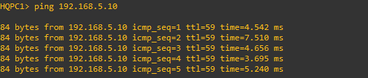
HQPC1>ping 192.168.5.10
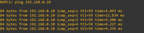
BOPC1>ping 192.168.0.10
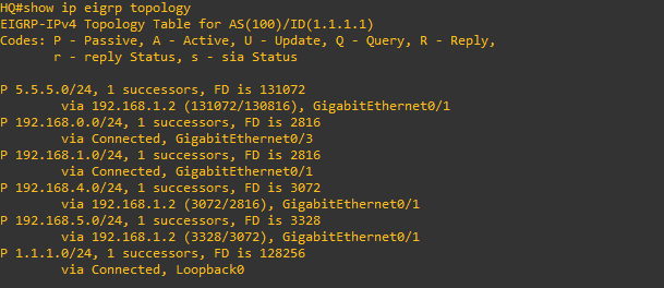
HQ# show ip eigrp topology
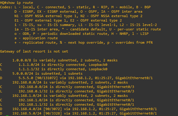
HQ#show ip route
PE1#show ip vrf

PE1#show ip vrf interfaces

PE1#show ip route vrf CUSTOMER
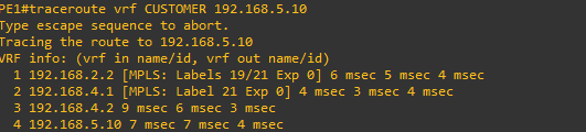
PE1#traceroute vrf CUSTOMER 192.168.5.10
PE1#show mpls interfaces

PE1#show mpls forwarding-table
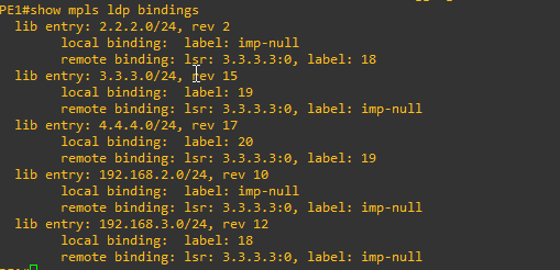
PE1#show mpls ldp bindings
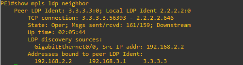
PE1#show mpls ldp neighbor
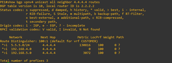
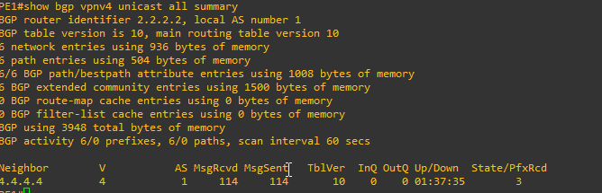
PE1#show bgp vpnv4 unicast all summary
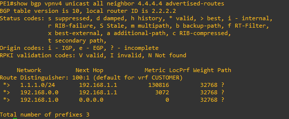
PE1#show bgp vpnv4 unicast all neighbor 4.4.4.4 advertised-routes
PE1#show bgp vpnv4 unicast all neighbor 4.4.4.4 routes