Cisco
All things Cisco
- Cisco IOS Switch Basic Setup
- Cisco IOS Router Static Route
- Cisco IOS Router on a Stick
- Cisco IOS Discovery Protocol
- Cisco IOS RIPv2 Protocol
- Cisco IOS EIGRP Protocol
- OSPF Open Shortest Path First Protocol
- Cisco IOS OSPF Protocol
- Cisco IOS OSPF Router ID
- Cisco IOS eBGP (External) Protocol
- BGP Path Attributes
- Cisco IOS Basic MPLS VPN
- Cisco IOS Configure Router as DHCP Server
- Cisco IOS Configure DHCP Relay with IP Helper Address
- Cisco IOS Configure Router as DNS Server
- Cisco IOS VRF-Lite
- Cisco IOS Site to Site VPN (Router)
- Cisco ASA 5505 Internet Access
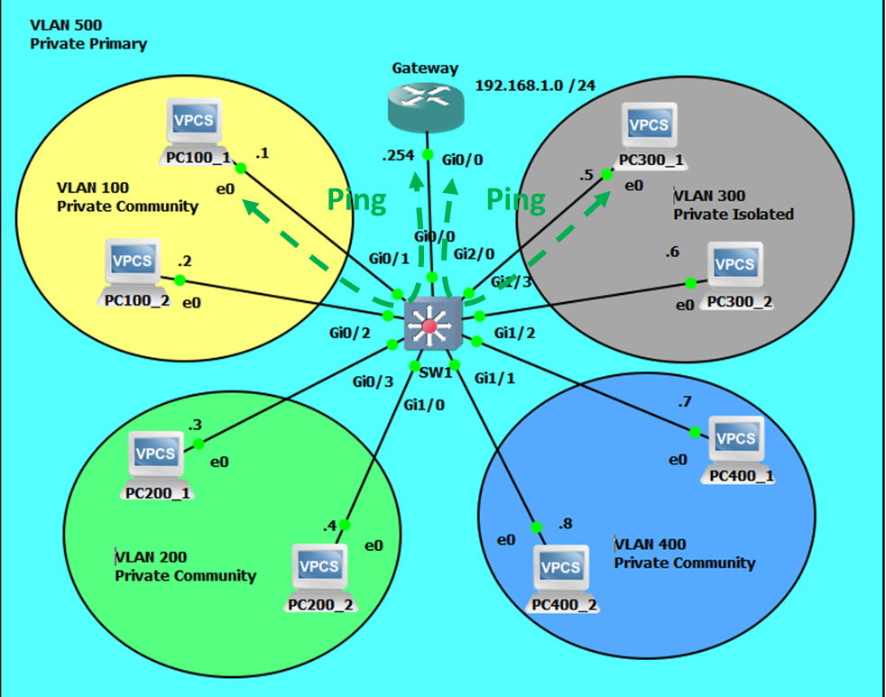
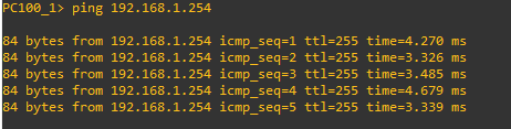
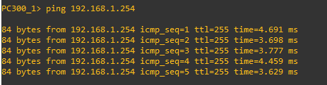
- Cisco IOS Private VLANs
Cisco IOS Switch Basic Setup
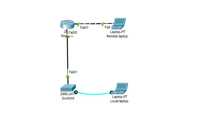
Network Topology
Router0 Configuration Commands
Router0>enable
Router0#configure terminal
Router0(config)# interface fastEthernet 0/1
Router0(config-if)#ip address 172.16.1.1 255.255.255.0
Router0(config-if)#no shutdown
Router0(config-if)#interface fastEthernet 0/0
Router0(config-if)#ip address 192.168.10.1 255.255.255.0
Router0(config-if)#no shutdown
Router0(config-if)#exit
Router0(config)#exit
Router0#show ip interface brief

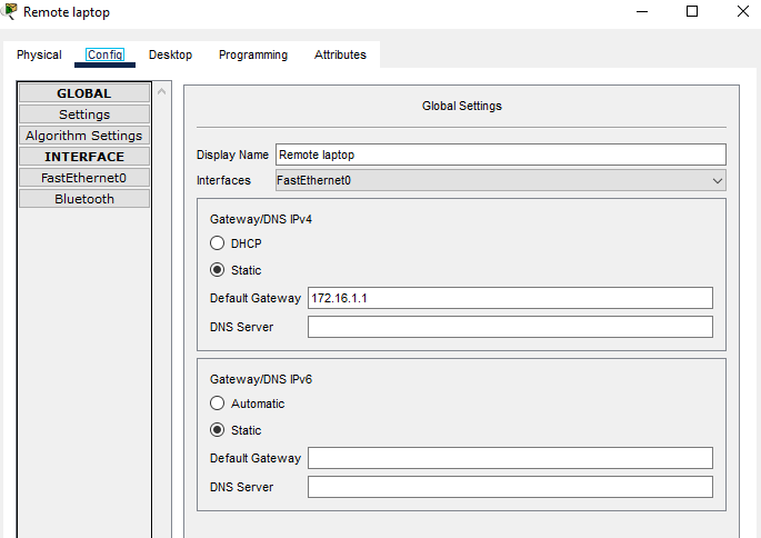
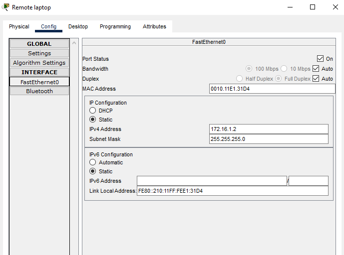
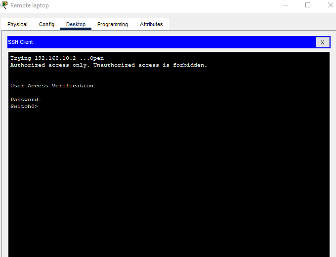
Remote Laptop Configuration
Switch0 Configuration Commands using Local Laptop and Console Cable
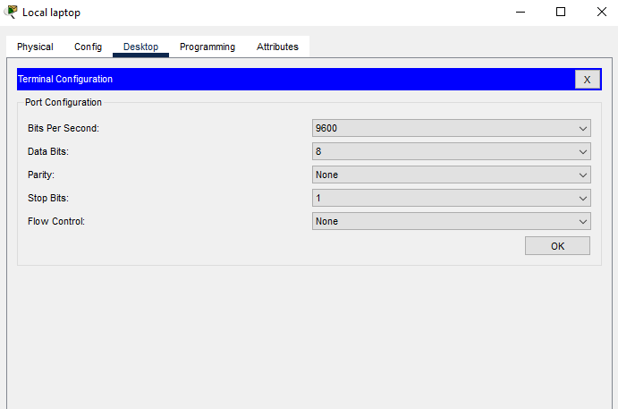
Connect to Switch0 using Terminal
Set hostname of the switch to Switch0
Switch>enable
Switch#configure terminal
Switch(config)#hostname Switch0
Switch0(config)#
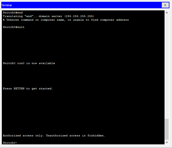
Configure the message of the day as "Authorized access only. Unauthorized access is forbidden."
Switch0(config)#banner motd #
Enter TEXT message. End with the character '#'.
Authorized access only. Unauthorized access is forbidden.#
Switch0(config)#end
Switch0#exit
Configure the password for privileged mode access as "cisco". The password must be md5 encrypted
Switch0>enable
Switch0#configure terminal
Switch0(config)#enable secret cisco
Switch0(config)#service password-encryption
Configure CONSOLE access with the following settings:
- Login enabled
- Password: ciscoconsole
- History size: 20 commands
- Timeout: 5m 30s'
- Synchronous logging
Switch0(config)#line con 0
Switch0(config-line)#password ciscoconsole
Switch0(config-line)#logging synchronous
Switch0(config-line)#login
Switch0(config-line)#history size 20
Switch0(config-line)#exec-timeout 5 30
Switch0(config-line)#exit
Switch0(config)#
Configure TELNET access with the following settings:
- Login enabled
- Password: ciscotelnet
- History size: 20 commands
- Timeout: 10m 45s
- Synchronous logging
Switch0(config)#line vty 0 15
Switch0(config-line)#password ciscotelnet
Switch0(config-line)#logging synchronous
Switch0(config-line)#login
Switch0(config-line)#history size 20
Switch0(config-line)#exec-timeout 10 45
Switch0(config-line)#exit
Switch0(config)#
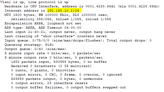
Configure the IP address of Switch0 as 192.168.10.2/24 and its default gateway IP (192.168.10.1).
Switch0(config)#interface vlan1
Switch0(config-if)#ip address 192.168.10.2 255.255.255.0
Switch0(config-if)#ip default-gateway 192.168.10.1
Switch0(config-if)#end
Switch0(config)#exit
Switch0>
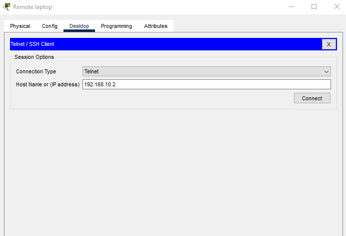
Test Telnet Connectivity from the Remote Laptop Using Telnet Client
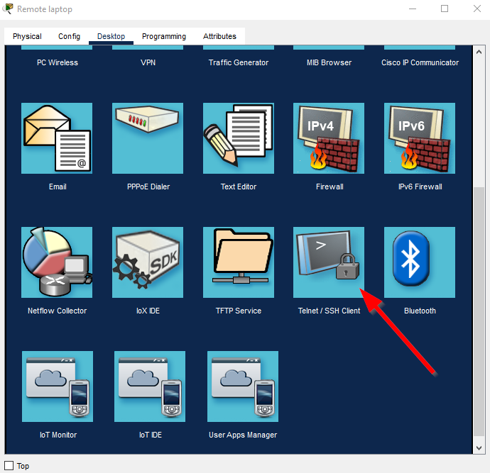
Change the Connection Type to Telnet and then put in Switch0's IP address. Then click Connect.
Notice the MOTD Banner and the prompt for the telnet password. Enter ciscotelnet.
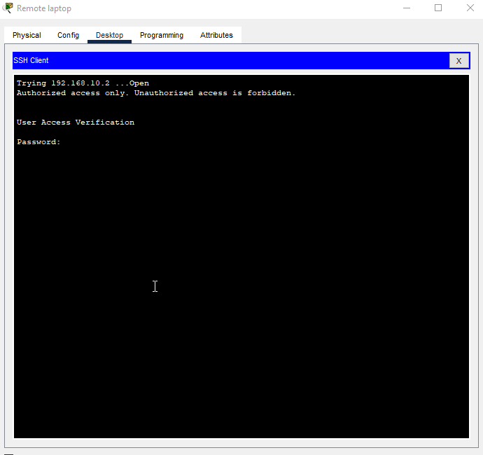
We're in!
Cisco Packet Tracer File
Cisco IOS Router Static Route
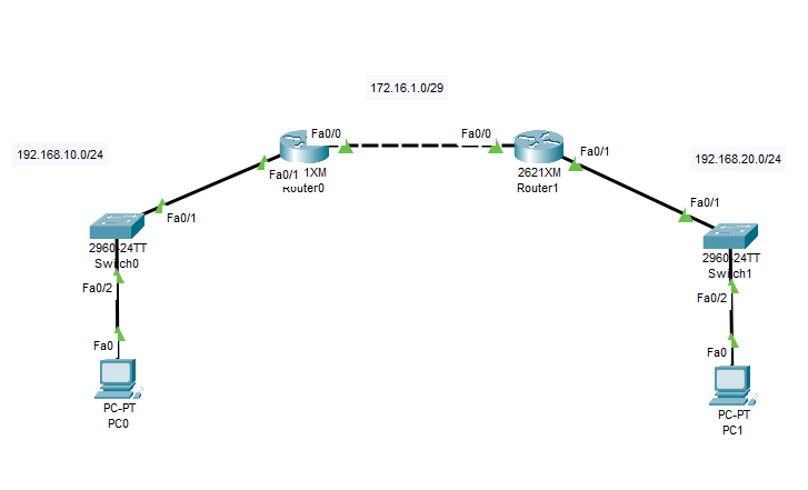
Network Topology
Router0 Configuration Commands
Router0>enable
Router0#configure terminal
Router0(config)# interface fastEthernet 0/0
Router0(config-if)#ip address 172.16.1.1 255.255.255.248
Router0(config-if)#no shutdown
Router0(config-if)#interface fastEthernet 0/1
Router0(config-if)#ip address 192.168.10.1 255.255.255.0
Router0(config-if)#no shutdown
Router0(config-if)#exit
Router0(config)#ip route 192.168.20.0 255.255.255.0 172.16.1.2
Router0(config)#exit
Router0#show ip interface brief

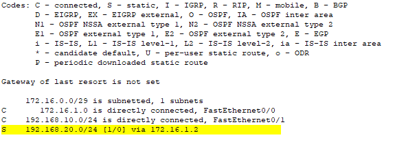
Router0#show ip route
Router1 Configuration Commands
Router1>enable
Router1#configure terminal
Router1(config)# interface fastEthernet 0/0
Router1(config-if)#ip address 172.16.1.2 255.255.255.248
Router1(config-if)#no shutdown
Router1(config-if)#interface fastEthernet 0/1
Router1(config-if)#ip address 192.168.20.1 255.255.255.0
Router1(config-if)#no shutdown
Router1(config-if)#exit
Router1(config)#ip route 192.168.10.0 255.255.255.0 172.16.1.1
Router1(config)#exit
Router1#show ip interface brief

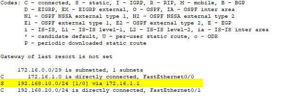
Router1#show ip route
Switch0 Configuration Commands
Switch0>enable
Switch0#configure terminal
Switch0(config)#int vlan1
Switch0(config-if)#ip address 192.168.10.2 255.255.255.0
Switch0(config-if)#ip default-gateway 192.168.10.1
Switch0(config-if)#no shutdown
Switch0(config-if)# exit
Switch0(config)#show interface vlan 1
Switch1 Configuration Commands
Switch1>enable
Switch1#configure terminal
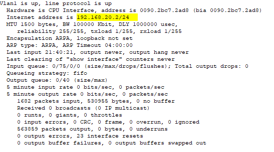
Switch1(config)#int vlan1
Switch1(config-if)#ip address 192.168.20.2 255.255.255.0
Switch1(config-if)#ip default-gateway 192.168.20.1
Switch1(config-if)#no shutdown
Switch1(config-if)# exit
Switch1(config)#show interface vlan 1
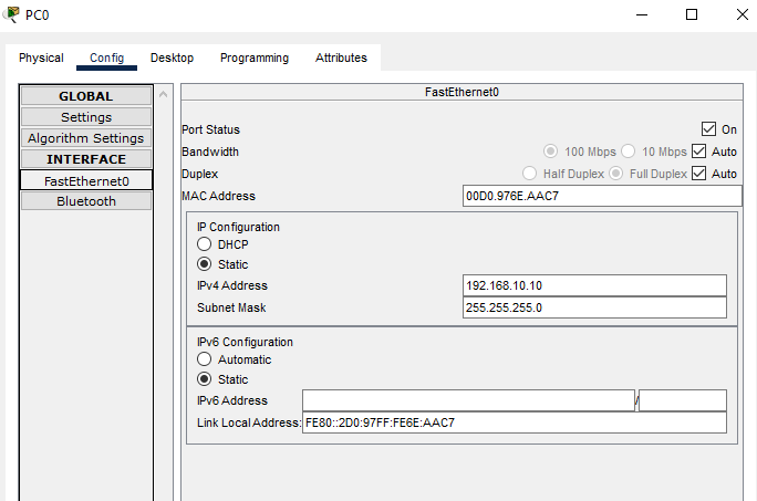
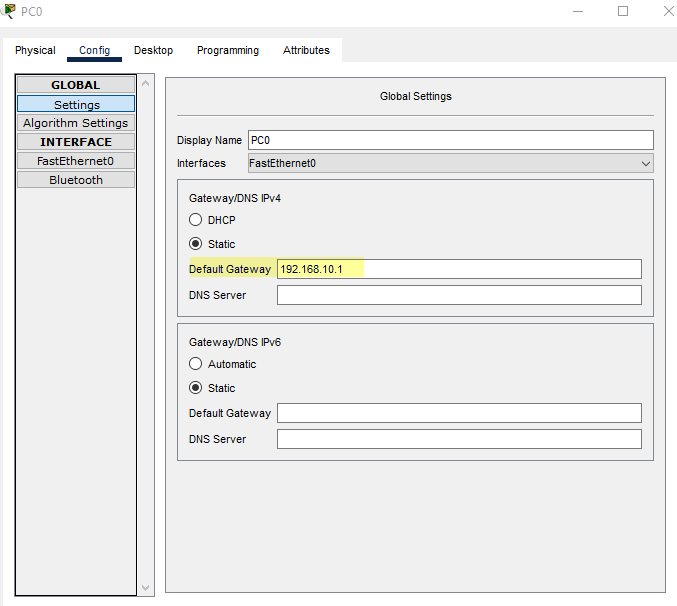
PC0 Configuration

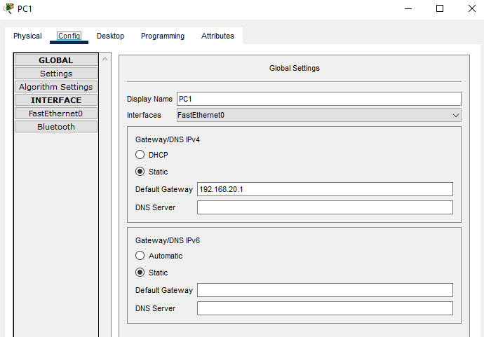
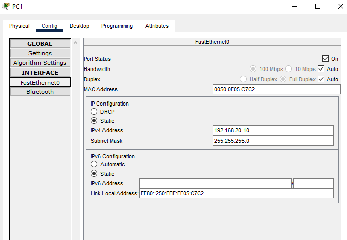
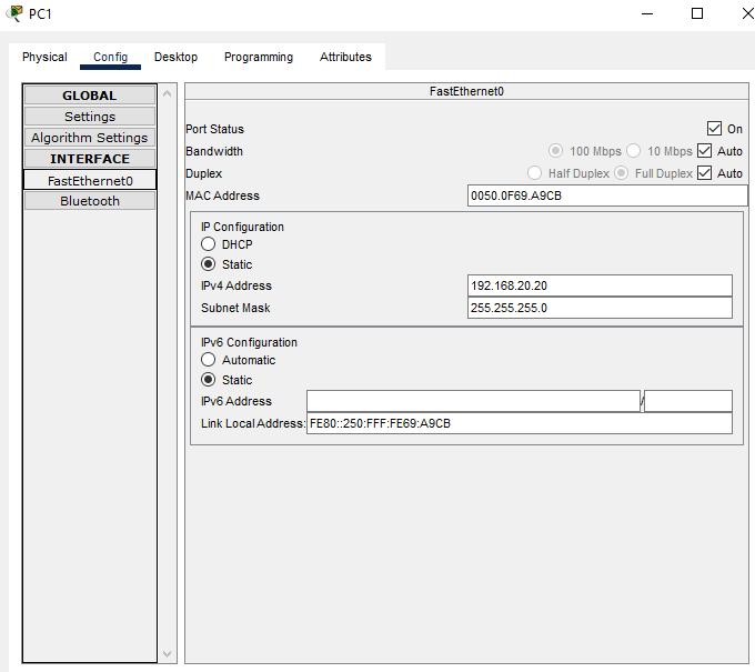
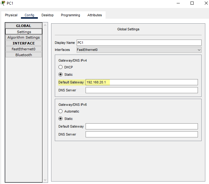
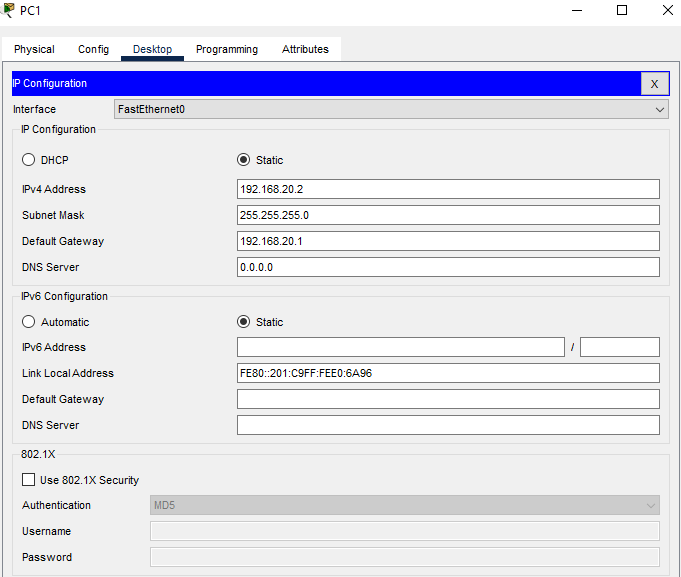
PC1 Configuration
Test Connectivity via Static Route
Cisco Packet Tracer File
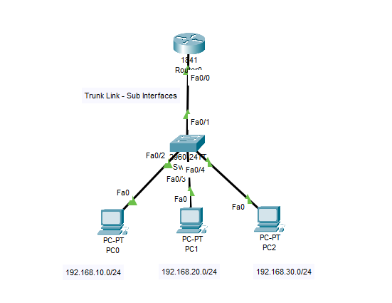
Cisco IOS Router on a Stick
Network Topology
Router0 Configuration Commands
Router0>enable
Router0#configure terminal
Router0(config)#interface fastEthernet 0/0
Router0(config-if)#no shutdown
Router0(config-if)#interface fastEthernet 0/0.10
Router0(config-subif)#encapsulation dot1q 10
Router0(config-subif)#ip address 192.168.10.1 255.255.255.0
Router0(config-if)#interface fastEthernet 0/0.20
Router0(config-subif)#encapsulation dot1q 20
Router0(config-subif)#ip address 192.168.20.1 255.255.255.0
Router0(config-if)#interface fastEthernet 0/0.30
Router0(config-subif)#encapsulation dot1q 30
Router0(config-subif)#ip address 192.168.30.1 255.255.255.0
Router0(config-subif)#end
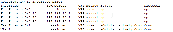
Router0#show ip interface brief
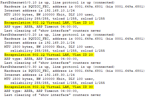
Router0#show interfaces
Switch0 Configuration Commands
Switch0>enable
Switch0#configure terminal
Switch0(config)#interface fastEthernet 0/1
Switch0(config-if)#switchport mode trunk
Switch0(config-if)#interface fastEthernet 0/2
Switch0(config-if)#switchport access vlan 10
Switch0(config-if)#interface fastEthernet 0/3
Switch0(config-if)#switchport access vlan 20
Switch0(config-if)#interface fastEthernet 0/4
Switch0(config-if)#switchport access vlan 30
Switch0(config-if)#end
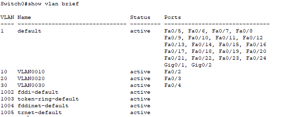
Switch0#show vlan brief
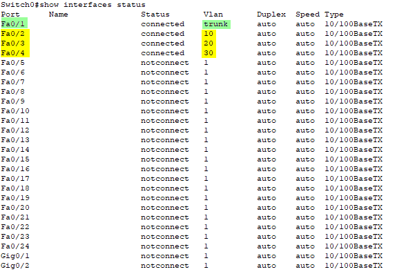
Switch0#show interfaces status
Configure the Three PCs
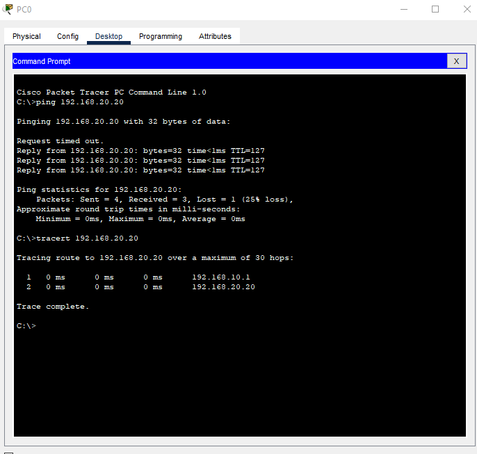
PC0

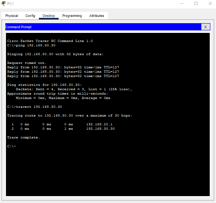
PC1
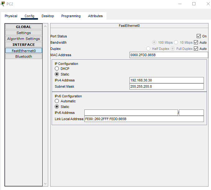
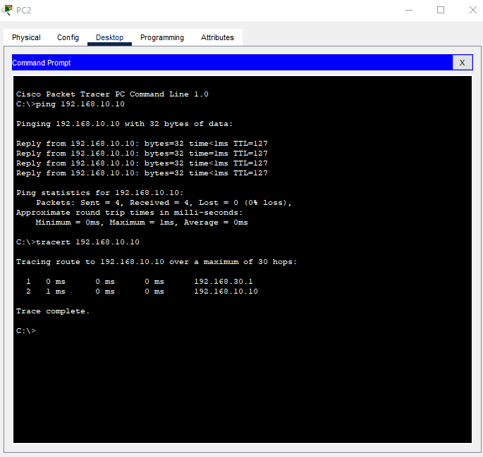
PC2

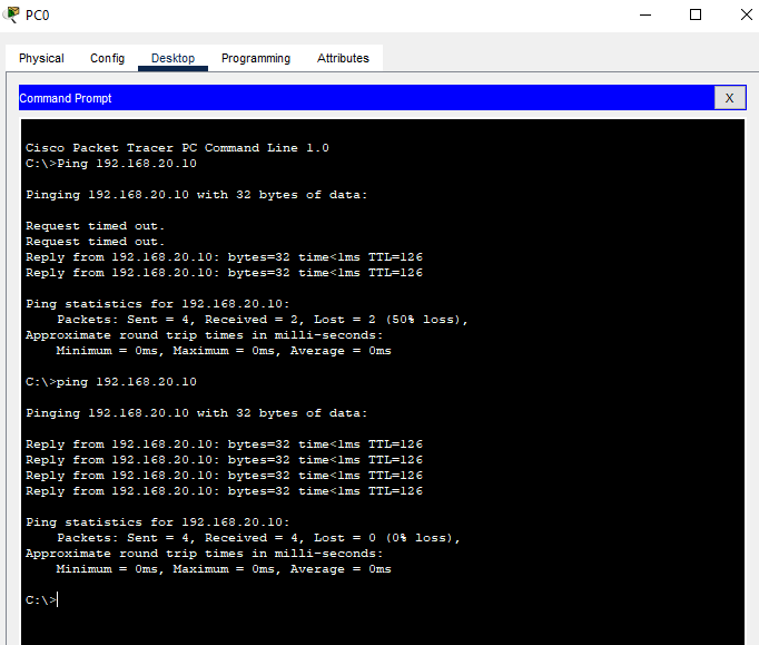
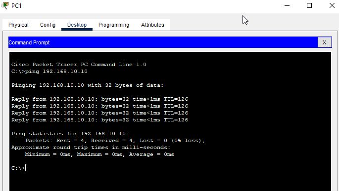
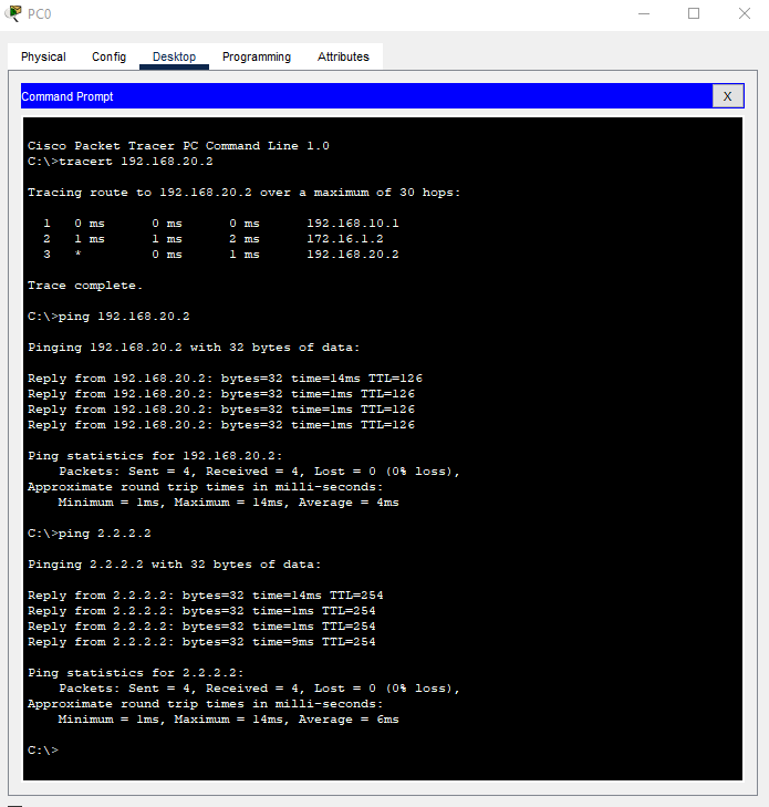
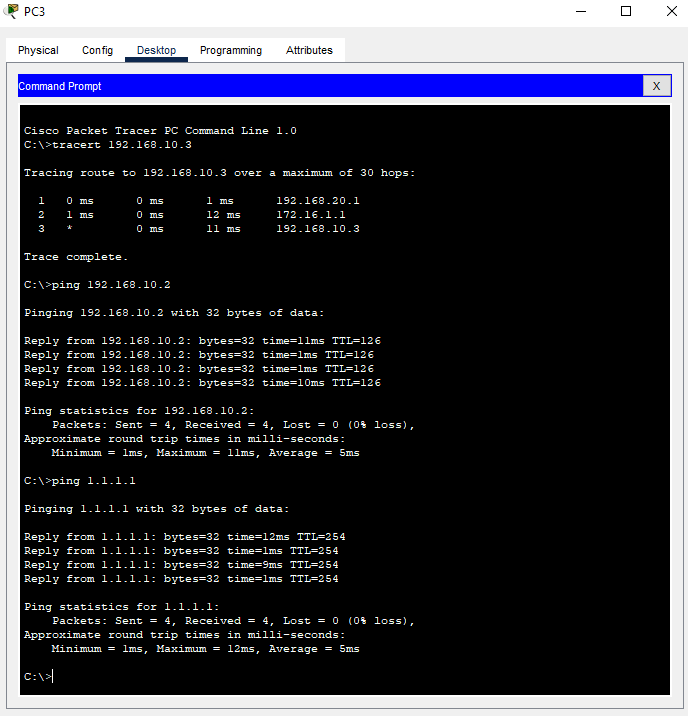
Test with Ping and Tracert
Cisco Packet Tracer File
Cisco IOS Discovery Protocol
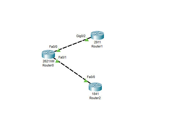
Network Topology
Premise
When you have a detailed topology map like the one above it is easy to know what interfaces and what devices you are working with. However, a topology map like this is often not readily available. Instead, you are on one end of the equation in a wiring closet or data center removed from the far side equipment and you are staring at a console screen like this.

And it is left to you to figure out what is connected to your device on the other end. What can you use to figure this out? Cisco provides some help by the way of the Cisco Discovery Protocol (CDP). CDP is enabled by default on Cisco devices and works on directly connected interfaces. The CDP messages are configured to broadcast every 60 seconds by default. This interval can be modified. When a device receives a CDP broadcast the information is stored in a table. Using the show CDP neighbors will display information about directly connected Cisco devices.
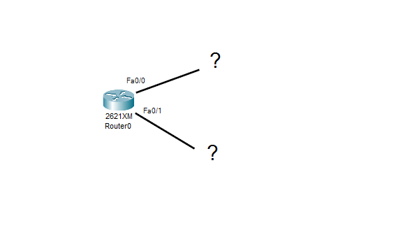
Now suppose instead of a nice all-filled-in topology diagram you have this. You have been told that there are routers connected to the other end of the Router0 interfaces. One router is a Cisco 1841 but the technician is not sure what the other router is. The interface connected to the 1841 is in the 192.168.10.0/24 network. The other interface should be configured within the 192.168.20.0/24 network.
Solution
Router0 Commands
Router0>enable
Router0#configure terminal
Router0(config)#interface fastEthernet 0/0
Router0(config-if)#no shutdown
Router0(config)#interface fastEthernet 0/1
Router0(config-if)#no shutdown
Router0(config-if)#end
Router0#show ip interface brief

As can be seen by the show ip interface brief command, the interfaces are up but there are no L3 IP addresses configured. This is something that will need to be addressed later. But for now, we can find out more about which devices are connected to which interfaces by using the show CDP commands. First, we will check that CDP protocol is configured and working on Router0
Router0#show cdp interface
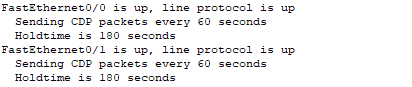
Yes, CDP is configured and sending packets every 60 seconds as is the default behavior. No let's see if there are any CDP packets coming from Cisco devices on the other in of the ethernet connections.
Router0#show cdp neighbors
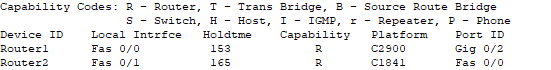
The results of the show cdp neighbors command indicates that there are Cisco attached devices. On the fast Ethernet 0/1 port the Cisco 1841 router is connected just as the technician had stated. On the fast Ethernet port 0/0 there is a Cisco 2900 router. In addition, we can see from the output that on the 1841 the connection is on fast Ethernet 0/0 while on the 2900 we are connected to gigabit Ethernet 0/2. If we want more details, we can use the command show cdp entry *
Router0#show cdp entry *
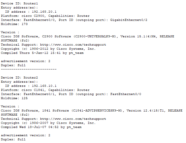
From this we can see the configured IP addresses of the two connected devices. We can verify that the connected device types are in fact routers. We can even see the Cisco IOS version installed on the routers. Finally, we can see that the CDP type is version 2 as shown by the 'advertisement version'.
Let's jump back into Router0 and configure some IP addressing now that we know the IP addresses on the far side of the connections.
Router0(config)#interface fastEthernet 0/0
Router0(config-if)#ip address 192.168.20.2 255.255.255.0
Router0(config)#interface fastEthernet 0/1
Router0(config-if)#ip address 192.168.10.2 255.255.255.0
Router0(config-if)#end
Router0#show ip interface brief
Router0#ping 192.168.10.1

Router0#ping 192.168.20.1

Success!
Cisco Packet Tracer File
Cisco IOS RIPv2 Protocol
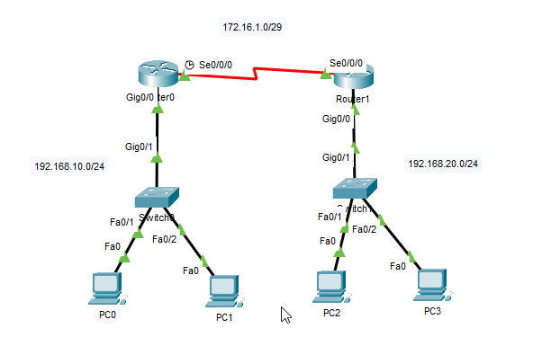
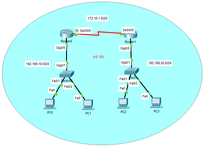
Network Topology
Router0 Configuration Commands
Router0>enable
Router0#configure terminal
Router0(config)#interface serial 0/0/0
Router0(config-if)#ip address 172.16.1.1 255.255.255.248
Router0(config-if)#no shutdown
Router0(config-if)#interface gigabitEthernet 0/0
Router0(config-if)#ip address 192.168.10.1 255.255.255.0
Router0(config-if)#no shutdown
Router0(config-if)#exit
Router0(config)#router rip
Router0(config-router)#version 2
Router0(config-router)#network 192.168.10.0
Router0(config-router)#network 172.16.1.0
Router1(config-router)#no auto-summary
Router0(config-router)#end
Router1 Configuration Commands
Router1>enable
Router1#configure terminal
Router1(config)#interface serial 0/0/0
Router1(config-if)#ip address 172.16.1.2 255.255.255.248
Router1(config-if)#no shutdown
Router1(config-if)#interface gigabitEthernet 0/0
Router1(config-if)#ip address 192.168.20.1 255.255.255.0
Router1(config-if)#no shutdown
Router1(config-if)#exit
Router1(config)#router rip
Router1(config-router)#version 2
Router1(config-router)#network 192.168.20.0
Router1(config-router)#network 172.16.1.0
Router1(config-router)#no auto-summary
Router1(config-router)#end
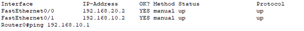
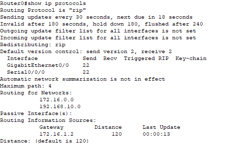
Verify RIPv2 Configuration
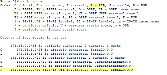
Router0#show ip route
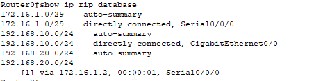
Router0#show ip rip database
Router0#show ip protocols
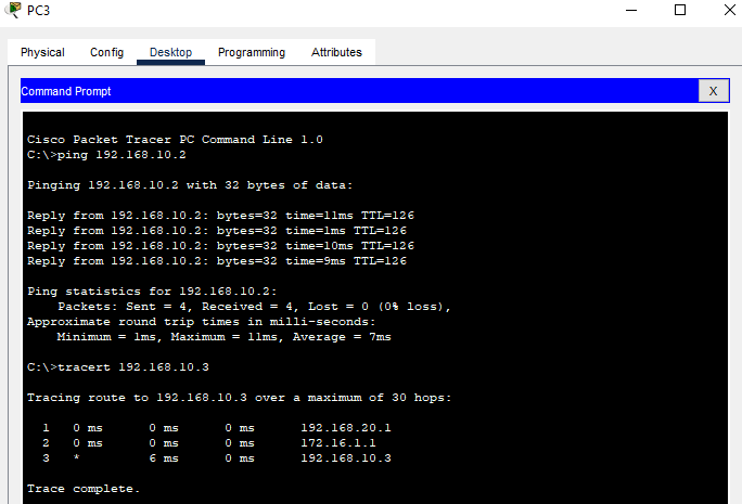
Ping and Tracert Check
Cisco Packet Tracer File
Cisco IOS EIGRP Protocol
Network Topology
Router0 Configuration Commands
Router0>enable
Router0#configure terminal
Router0(config)#interface serial 0/0/0
Router0(config-if)#ip address 172.16.1.1 255.255.255.248
Router0(config-if)#no shutdown
Router0(config-if)#interface gigabitEthernet 0/0
Router0(config-if)#ip address 192.168.10.1 255.255.255.0
Router0(config-if)#no shutdown
Router0(config-if)#exit
Router0(config)#router eigrp 100
Router0(config-router)#network 192.168.10.0 0.0.0.0
Router0(config-router)#network 172.16.1.0 0.0.0.0
Router0(config-router)#no auto-summary
Router0(config-router)#end
Router1 Configuration Commands
Router1>enable
Router1#configure terminal
Router1(config)#interface serial 0/0/0
Router1(config-if)#ip address 172.16.1.2 255.255.255.248
Router1(config-if)#no shutdown
Router1(config-if)#interface gigabitEthernet 0/0
Router1(config-if)#ip address 192.168.20.1 255.255.255.0
Router1(config-if)#no shutdown
Router1(config-if)#exit
Router1(config)#router eigrp 100
Router1(config-router)#network 192.168.20.0 0.0.0.0
Router1(config-router)#network 172.16.1.0 0.0.0.0
Router0(config-router)#no auto-summary
Router1(config-router)#end
Comments on a Couple of Configuration Items
A couple of notes about the configurations. First, the network commands show a wildcard of 0.0.0.0, this denotes an exact match for the specific IP on the interfaces. I could have also made the command be for a subnet with network 192.168.10.0 0.0.0.255 It was simply a preference on my part for this configuration.
Second, the command no auto-summary. EIGRP is a routing protocol that supports auto summarization. This isn't very intuitive to understand. Auto summarization in EIGRP means that it will automatically advertise the classful A, B, or C subnet if it is not told otherwise. Let's take a look at another network topology to demonstrate the auto-summary effect.
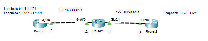
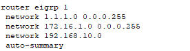
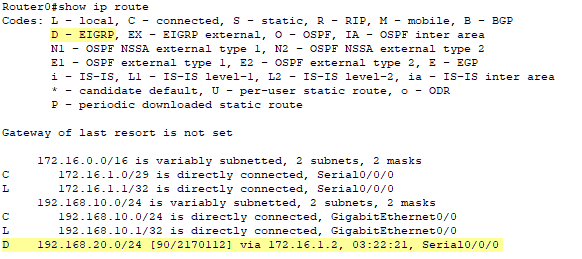
In the above example there are three routers configured for eigrp. In the initial setup Router0 and Router2 have auto-summary on for EIGRP. All three networks 192.168.2.0, 172.16.1.0, and 1.1.1.0 are configured in the EIGRP router for Router0.
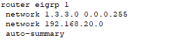
Similarly, Router 2 has EIGRP configured and 1.3.3.0 and 192.168.20.0 are configured. Also, auto-summary has been explicitely turned on.
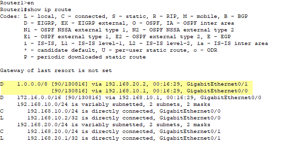
Router1 is pretty vanilla with EIGRP configured and advertising the 192.168.10.0 and 192.168.20.0 networks. No auto-summary is on for Router1. The interesting thing is taking a look at the routing tables of each of the routers to see what auto-summary does in this scenario. And how it will break the routing. Let's look at Router0 first.
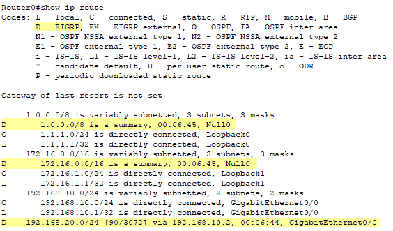
The 1.1.1.0 /24 network has been summarized the classful A network of 1.0.0.0 /8. Similarly, the 172.16.1.0 /24 has been summarized to the classful B network of 172.16.0.0 /16. This isn't necessary bad when you just look at it from Router0's perspective but hold that thought until we take a closer look at Router1 in a moment. One last note for Router0, the network 192.168.10.0 /24 is as expected becasue it is already a class C network.
No let's look at Router2 and then we will get to Router1.
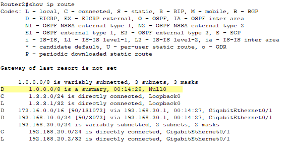
Now, you can already start to see the problem, Router2 is advertising a summarized classful A for 1.0.0.0 /8 just as Router0 was. And what does that do to Router1, confuses the heck out of its routing table, that's what! Let's look.
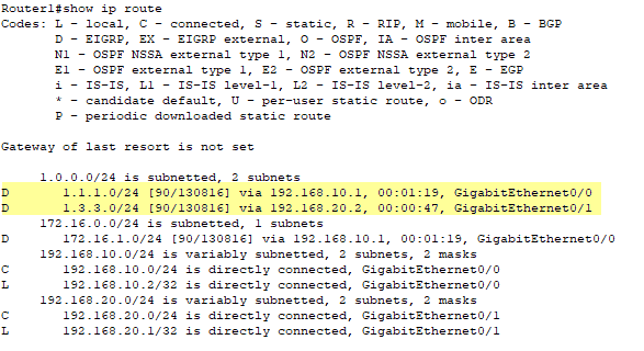
So, now Router1 is advertising that 1.0.0.0 /8, which is the summarized subnet for both 1.1.1.0 and 1.3.3.0 is reachable through both the other routers. This is what unchecked auto-summary can do to EIGRP if you are not careful. The fix is to turn off auto-summary in Router0 and Router1. And problem resolved. Take a look at Router1, the one that was so confused before we turned off auto-summary, it has the correct routes now.
Back to the EIGRP Configuration
Verify the configuration
Router0#show ip route
Router0#show ip eigrp neighbors
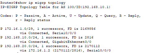
Router0#show ip eigrp topology
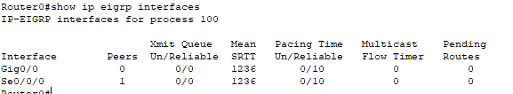
Router0#show ip eigrp interfaces
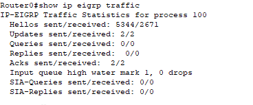
Router0#show ip eigrp traffic
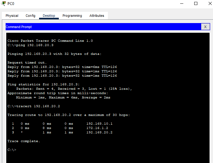
Ping and Tracert Tests
Cisco Packet Tracer Files
OSPF Open Shortest Path First Protocol
OSPF Limerick
There once was a routing protocol
OSPF was its name, it was droll
It spread updates with care
To routers everywhere
So that packets would never grow stale.
- Most widely used interior gateway routing protocol
- Open standard (non-proprietary)
- Fast convergence
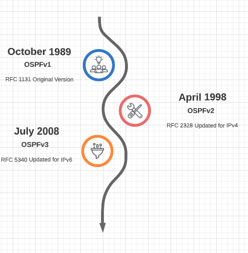
- It's been around since 1989.
How does it differ from other routing protocols?
Distance Vector ProtocolsDistance Vector routing protocols base their decisions on the best path to a given destination based on the distance. If the distance metric is hop, then each time a packet goes through a router, a hop is considered to have traversed. The route with the least number of hops to a given network is concluded to be the best route towards that network. The vector shows the direction to that specific network. Distance vector protocols send their entire routing table to directly connected neighbors. |
Link State ProtocolsLink state protocols are also called shortest-path-first protocols. Link state routing protocols have a complete picture of the network topology. Hence they know more about the whole network than any distance vector protocol. Three separate tables are created on each link state routing enabled router. One table is used to hold details about directly connected neighbors, one is used to hold the topology of the entire internetwork and the last one is used to hold the actual routing table. Link state protocols send information about directly connected links to all the routers in the network. |
| RIP and IGRP | OSPF and IS-IS (EIGRP is considered a hybrid protocol because it uses both distance vector and link state.) |
| Only communicates with neighbor routers | Communicates with all other routers in an area |
| Calculates path based on distance and vector | Calculates shortest path based on link-state parameters |
| Passes entire routing table to directly connected neighbor routers | Passes link-state routing updates to other routers |
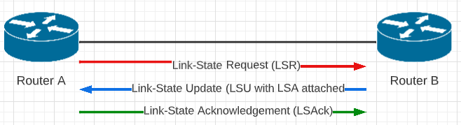
Link-State Routing
1. LSRRouter A send a link-state request (LSR) to gather route information from the neighbor router -- Router B |
2. LSURouter B replies with a Link -State Update (LSU) containing the requested Link-State Advertisement (LSA) information. |
3. LSAckRouter A receives the LSU with LSA attached and sends a Link-State Acknowledgement (LSAck) back to Router B |
Dijkstra's Algorithm
The speed of OSPF can be attributed to the Dijkstra Algorithm (Shortest Path First)
Dijkstra's algorithm is a method for finding the shortest path between two points in a graph. The graph could represent, for example, a map with cities as nodes and roads as edges, where the length of the edges represents the distance between the cities. The algorithm starts at one node, called the "source" node, and explores all the paths to the other nodes, called "destination" nodes, in the graph. It keeps track of the shortest path to each destination node that it has found so far, and updates this information as it explores new paths.
At each step, the algorithm selects the destination node that can be reached with the shortest known path from the source node, and explores the paths to all the other nodes that can be reached from this node. This process is repeated until the algorithm has found the shortest path to the destination node that you are interested in.
The algorithm is called Dijkstra's algorithm because it was invented by a Dutch computer scientist named Edsger W. Dijkstra in the 1950s. Dijkstra's algorithm is also famous because it's the first algorithm that uses a priority queue(heap) rather than a queue to proceed from one node to the other.
It is often used for finding the shortest path in a navigation or transportation network, or for routing packets of data in a computer network
|
|
Illustration of Dijkstra's algorithm finding a path from a start node (lower left, red) to a goal node (upper right, green) in a robot motion planning problem. Open nodes represent the "tentative" set (aka set of "unvisited" nodes). Filled nodes are the visited ones, with color representing the distance: the greener, the closer. Nodes in all the different directions are explored uniformly, appearing more-or-less as a circular wavefront as Dijkstra's algorithm uses a heuristic identically equal to 0. * source: https://en.wikipedia.org/wiki/Dijkstra%27s_algorithm |

OSPF Path Selection
- Link-state information is flooded throughout the network, from router to router within an area, enabling all the routers within the area to have a synchronized and identical map of the network area.
- The Dijkstra's Algorithm (Shortest Path First) is then applied to this map of information to calculate the best (shortest) path.
- Once the Dijkstra Algorithm is applied and discovers the best routes the routes are applied to the routing table in the routers.
OSFP History
OSPF Areas
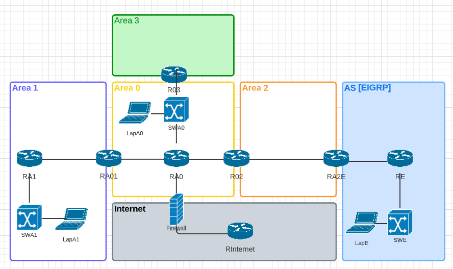
An OSPF Area is a network where routers all have the same routing information (LSAs) Network updates are localized per area and routers share topology information within the second table mentioned above (topology table). To reduce the size of the topology table in very large OSPF implementations the areas can be broken up into different OSPF area limits. Thus, the network updates will only be applied to the specifically identified area.
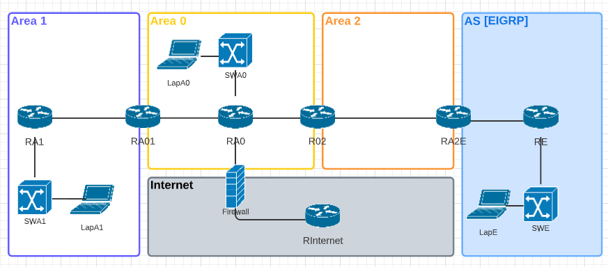
Area 0 is the Backbone and all other areas must connect back to Area 0
Adding an Area3 through Area 1 (as in the diagram below) would not be a correct or allowed configuration as Area 3 is NOT connected to Area 0, the Backbone.
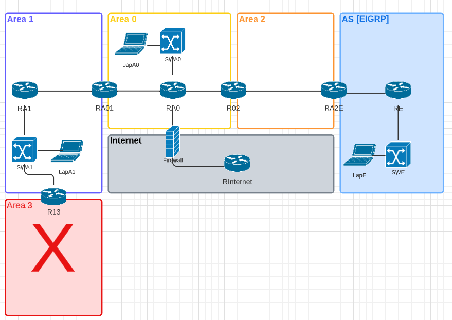
Adding Area 3 by connecting it to the backbone is the correct method for adding another OSPF Area as in the updated diagram below.
OSPF Neighbor Requirements
- Must be on the same Area
- Must match the following fields:
- Hello timer - the interval in seconds that a router sends hello messages out of an OSPF-enabled interface
- Dead timer - the time in seconds that an OSPF enabled interface will wait to receive a hello message from a neighbor before considering that neighbor to be down.
- Authentication
- Maximum transmission unit (MTU)
- Stub flags
- Hello timer - the interval in seconds that a router sends hello messages out of an OSPF-enabled interface
Hello timer Defaults: Sent every 10 seconds on broadcast or P2P networks. Sent every 30 seconds on non-broadcast multiple assess networks (NBMA) (i.e.; Frame Relay). Hello packets are sent to all other routers to the following broadcast addresses depending on IP version
- IPv4 - 224.0.0.5
- IPv6 - FF02::5
When sending Hello packets to designated routers the following addresses are used. What is a designated router? See Below.
- IPv4 - 224.0.0.6
- IPv6 - FF02::6
Dead timer Defaults: 4 times the hello timer.
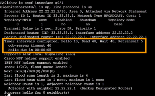
Wait timer is the number of seconds a router waits for the designated router or backup designated router to be advertised before beginning an election.
Retransmit is the number of seconds a router waits before retransmitting an OSPF packet that has not been acknowledged.
How to Change the Various Intervals
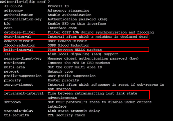
Router0(config)# interface gigabitEthernet 0/1
Router0(Config-if)#ip ospf hello-interval 20
Designated Router (DR) and Backup Designated Router (BDR)
Router adjacencies are neighbor routers that share LSUs and database description packets.
A large network could have a huge number of adjacencies as show by this formula:
[n*(n-1]/2So for 4 routers the number of adjacencies would be [4*(4-1)]/2 = 6. And for 10 the number of adjacencies would be [10*(10-1)]/2 = 45. As you can see the number of adjacencies becomes large very quickly. And a router will not be 'close' to all these adjacencies. Instead, an OSPF router is close to a specific router (neighbor) and that router is deemed the designated router (DR). And they also form an adjacency with a backup designated router (BDR). This is to reduce the adjacency volume.
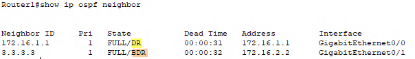
How does a router select its DR and BDR?
- Priority level (default is 1) The higher the priority the better.
- To adjust the priority level go to the interface global config and enter
Router1(config-if)# ip ospf priority [#]
-
- If you do not want a router to be considered as a DR or BDR set the priority level to zero (0) and it will no longer participate in the election.
- Router ID
- Router ID can be configured
Router1(config)#router ospf 1
Router1(config-router)#router-id [id]
- Loopback interface IP address
- Interface IP address
Not all network types conduct a DR/BDR election
| Network Type | DR/BDR Election? |
| Point to Point | No |
| Broadcast | Yes |
| Non broadcast multiple access (NMBA) | Yes |
| Point to Multipoint | No |
Area Border Router (ABR)
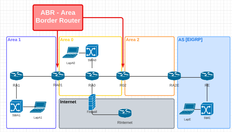
Typically an ABR has more processing power that an non ABR since they will have to store the routing tables for multiple OSPF Areas.
Autonomous System Boundary Router (ASBR)
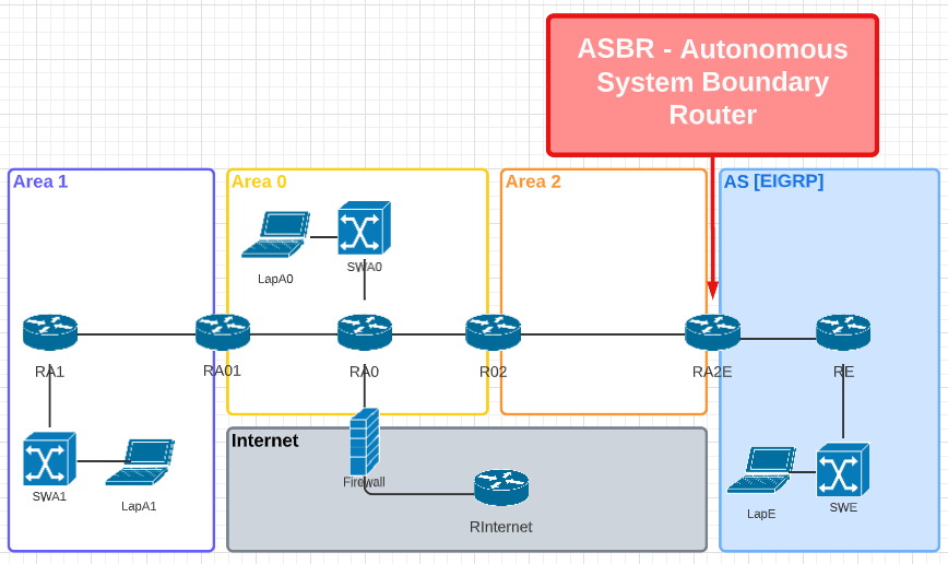
This router has one interface connected to OSPF and another interface with an entirely different routing protocol (i.e.; EIGRP)
LSA Types
- Type 1: Router LSA - this LAS type is what the routers use to advertise directly attached networks.
- Type 1: Network LSA - used in transit networks for DR/BDR elections
- No need for Type 2 Network LSA in Point to Point (except Frame Relay) or Point to Multipoint
- No need for Type 2 Network LSA of links going to end devices
- Type 3: Summary LSA - these LSAs come into play for Area Border Routers (ABR)
- Type 4 and Type 5 LSAs are created when an OSPF network is connected to another autonomous system (i.e.; EIGRP)
- Type 4: Summary ASBR LSA
- Created by an ABR to tell an Area how to reach and ASBR
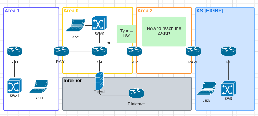
-
- Type 5: AS External LSA
- Type 5 is created by the ASBR to advertise networks in different autonomous systems
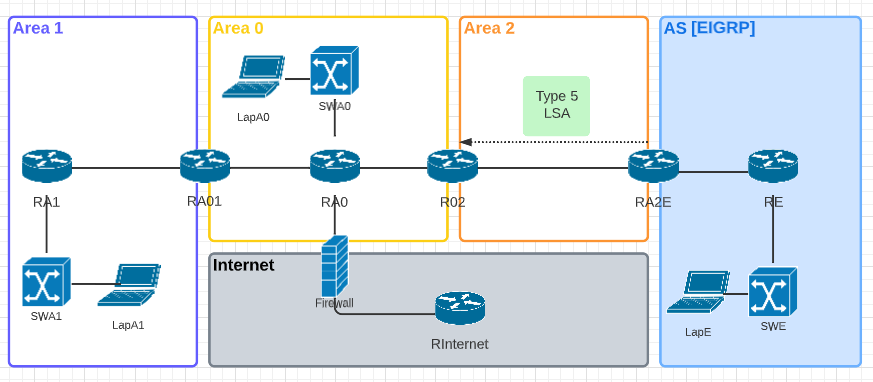
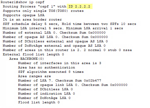
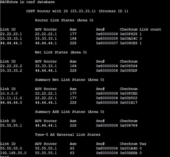
Router0#show ip ospf database
Stub Areas
An area that is only connected to the backbone and is not connected to any other autonomous systems
Route Summarization
In IPv4 networking, route summarization, also known as route aggregation, is a technique used to reduce the number of routing table entries on a router. This is done by grouping together several smaller networks into a single, larger network, and then advertising the summary route to other routers instead of the individual smaller networks.
For example, imagine a network with several subnets, such as 10.1.1.0/24, 10.1.2.0/24, 10.1.3.0/24, and so on. Instead of having a separate routing table entry for each of these subnets, route summarization allows a router to group them together into a single network, such as 10.1.0.0/22. This single entry will take the place of all the individual entries, reducing the size of the routing table and making it more efficient.
Route summarization is done by using a mask (also called a subnet mask) that is longer than the original subnet mask. This allows a group of subnets to be represented by a single IP address and mask.
The benefit of this technique is that it can help reduce the number of routing table entries and improve the performance of the routing process. By reducing the size of the routing table, routers can make faster and more efficient routing decisions. It also can help to reduce the amount of routing information that needs to be exchanged between routers.
It's important to note that while route summarization can help to improve the scalability and performance of a network, it can also create potential problem like black hole routing, where packets might be dropped if they are not delivered to the correct destination. Therefore, it's important to be mindful of the address space being used and make sure that the summary route being advertised not overlap with other routes that exist in the network.
Example
| Decimal | Octet 1 | Octet 2 | Octet 3 | Octet 4 |
| 192.168.8.0 | 11000000 | 10101000 | 00001000 | 00000000 |
| 192.168.9.0 | 11000000 | 10101000 | 00001001 | 00000000 |
| 192.168.10.0 | 11000000 | 10101000 | 00001010 | 00000000 |
| 192.168.11.0 | 11000000 | 10101000 | 00001011 | 00000000 |
| SUMMARY IP | 11000000 | 10101000 | 00001000 | 00000000 |
| 192 | 168 | 8 | 0 | |
| Subnet Mask | 11111111 | 11111111 | 11111100 | 00000000 |
| /22 | 255 | 255 | 252 | 0 |
Summarization Result = 192.168.8.0 with subnet 255.255.252.0 (/22)
Cisco IOS OSPF Protocol
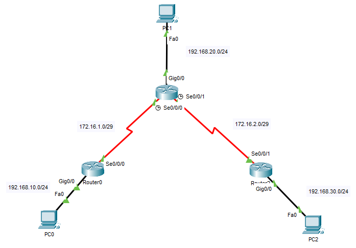
Network Topology
Router0 Configuration Commands
Router0>enable
Router0#configure terminal
Router0(config)#interface serial 0/0/0
Router0(config-if)#ip address 172.16.1.2 255.255.255.248
Router0(config-if)#no shutdown
Router0(config-if)#interface gigabitEthernet 0/0
Router0(config-if)#ip address 192.168.10.1 255.255.255.0
Router0(config-if)#no shutdown
Router0(config-if)#exit
Router0(config)#router ospf 1
Router0(config-router)#network 192.168.10.0 0.0.0.255 area 0
Router0(config-router)#network 172.16.1.0 0.0.0.7 area 0
Router0(config-router)#end
Router1 Configuration Commands
Router1>enable
Router1#configure terminal
Router1(config)#interface serial 0/0/0
Router1(config-if)#ip address 172.16.1.1 255.255.255.248
Router1(config-if)#no shutdown
Router1(config)#interface serial 0/0/1
Router1(config-if)#ip address 172.16.2.1 255.255.255.248
Router1(config-if)#no shutdown
Router1(config-if)#interface gigabitEthernet 0/0
Router1(config-if)#ip address 192.168.20.1 255.255.255.0
Router1(config-if)#no shutdown
Router1(config-if)#exit
Router1(config)#router ospf 1
Router1(config-router)#network 192.168.20.0 0.0.0.255 area 0
Router1(config-router)#network 172.16.1.0 0.0.0.7 area 0
Router1(config-router)#network 172.16.2.0 0.0.0.7 area 0
Router1(config-router)#end
Router2 Configuration Commands
Router2>enable
Router2#configure terminal
Router2(config)#interface serial 0/0/0
Router2(config-if)#ip address 172.16.2.2 255.255.255.248
Router2(config-if)#no shutdown
Router2(config-if)#interface gigabitEthernet 0/0
Router2(config-if)#ip address 192.168.30.1 255.255.255.0
Router2(config-if)#no shutdown
Router2(config-if)#exit
Router2(config)#router ospf 1
Router2(config-router)#network 192.168.30.0 0.0.0.255 area 0
Router2(config-router)#network 172.16.2.0 0.0.0.7 area 0
Router2(config-router)#end
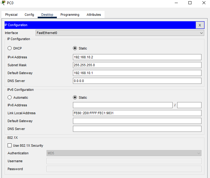
PC Configurations

Verify OSPF Configuration
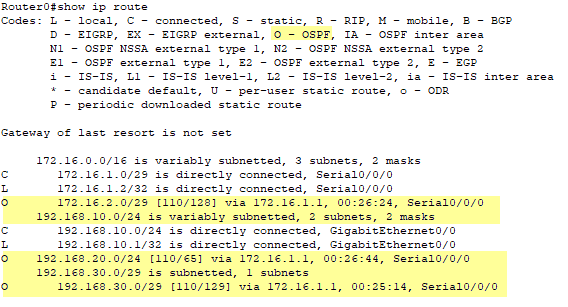
Router0#show ip route
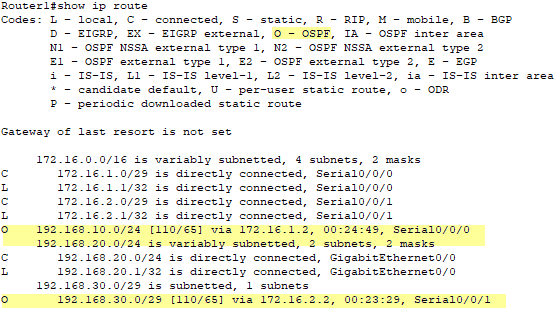
Router1#show ip route
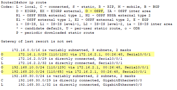
Router2#show ip route
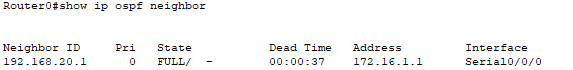
Router0# show ip ospf neighbor
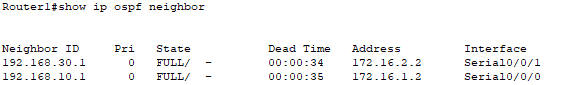
Router1#show ospf neighbor
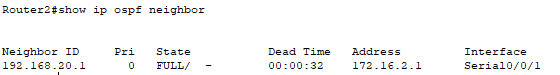
Router2#show ip ospf neighbor
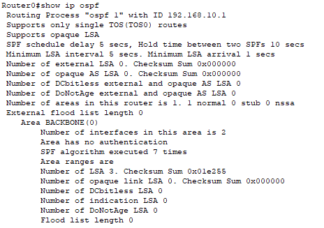
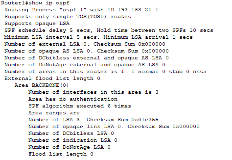
Router0#show ip ospf
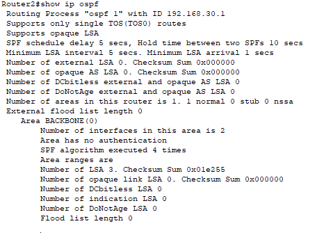
Router1#show ip ospf
Router2#show ip ospf
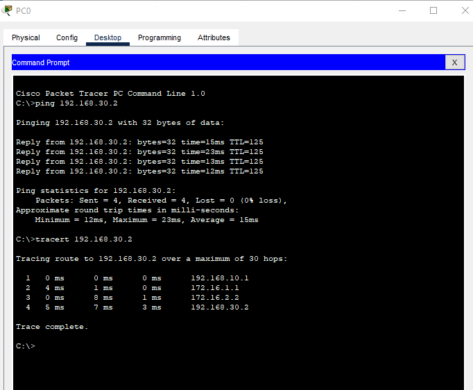
Ping and Tracert Checks
Cisco Packet Tracer File
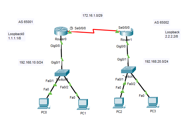
Cisco IOS OSPF Router ID
Network Topology
What is the OSPF Router ID (RID)?
The OSPF Router ID (RID) is a 32-bit value used to uniquely identify an OSPF router in a network. The Router ID takes the form of an IPv4 network address (i.e.; 1.1.1.1) It is used by OSPF routers to identify themselves to each other, and is also used as a key for certain OSPF data structures. The RID is typically chosen as the highest IP address of a router's interfaces that are configured for OSPF. If there are multiple interfaces with the same IP address, the RID will be chosen based on the interface's MAC address or on the order in which the interfaces were configured. The RID is used in the OSPF header of OSPF packets, and is also used in the LSA (Link State Advertisement) packets that OSPF routers exchange to form and maintain their routing tables.
How is the OSPF Router ID Selected?
A router chooses its OSPF Router ID (RID) based on the following priority:
- The highest IP address of a loopback interface that is configured for OSPF. A loopback interface is a virtual interface that is always up, and is typically used for management purposes.
- If there is no loopback interface configured, the highest IP address of a physical interface that is configured for OSPF.
- If there are multiple interfaces with the same IP address, the RID will be chosen based on the interface's MAC address.
- If all above methods fails to get a unique RID, the router will choose the RID based on the order in which the interfaces were configured.
It is important to note that, once chosen, the RID cannot be changed without restarting the OSPF process on the router. It is also important that all OSPF routers in a single OSPF domain must have unique RIDs.
Router ID in Action with Network Topology Above
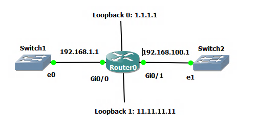
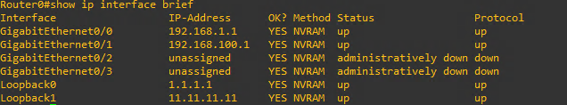
The topology above has two physical interfaces and two Loopback interfaces.
Router0# show ip interface brief
We can start the OSPF router process with the following command:
Router0(config)#router ospf 1
Router0(config-router)end
Now let's check the OSPF Router ID by issuing the command:
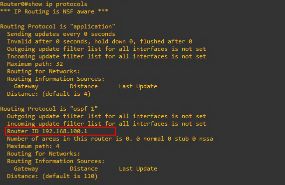
Router0#show ip protocols
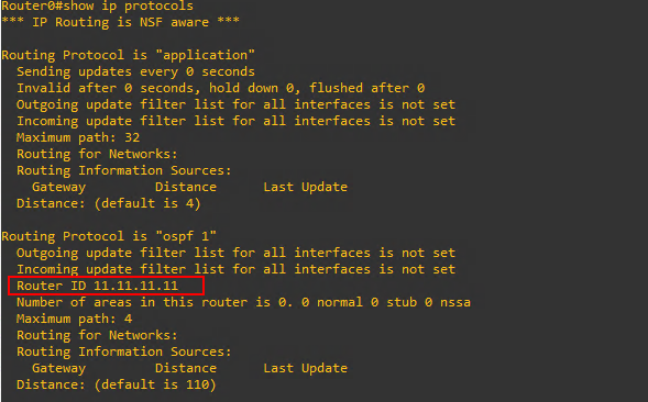
As can be seen above the ospf 1 process has chosen the Loopback interface with the highest IP address as its Router ID as we expected from #1 in the explanation above. Now let's remove the Loopback interfaces and see how that effects the OSPF Router ID.
Router0#configure terminal
Router0(config)#no interface loopback 0
Router0(config)#no interface loopback 1
Router0(config)#do show ip interface brief
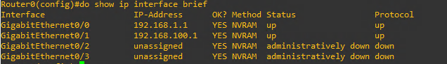
Confirmed that the Loopback interfaces have been removed. Let's check the OSPF Router ID now.
Router0(config)#end
Router0#show ip protocols
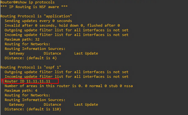
The Router ID has not changed! Just like the note above states the OSPF Router ID once chosen cannot be changed without a restart of the OSPF process. How can we restart the OSPF process? With this command:
Router0#clear ip ospf process
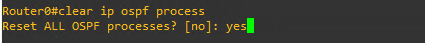
Now we can check the Router ID again.
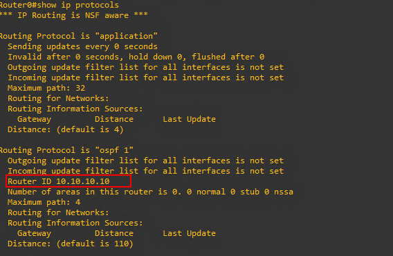
Router0#show ip protocols
After the reset of the OSPF process the Router ID has been selected from the physical interface with the highest IP address. Again, just like we would expect from #2 from the explanation above.
Now, what if we did not want the OSPF process to choose it's own Router ID? What if we wanted to manually set the Router ID, can we do that? Yes! As long as we make sure to set it in the correct format of the 32-bit value with a 4 octet IPv4 decimal notation address.
Router0#configure terminal
Router0(config)#router ospf 1
Router0(config-fouter)#router-id 10.10.10.10
Router0(config-router#end
Router0#show ip protocols
As you can see the Router ID is now set to what we manually entered 10.10.10.10.
Cisco IOS eBGP (External) Protocol
Network Topology
As of Cisco Packet Tracer 8.2 internal BGP (iBGP) is not supported only external BGP (eBGP) is supported. If you try and configure iBGP on Packet Tracer, you will see the following message.

So, in this example the focus will be on setting up eBGP between two separate autonomous systems.
Router0 Configuration Commands
Router0>enable
Router0#configure terminal
Router0(config)#interface serial 0/0/0
Router0(config-if)#ip address 172.16.1.1 255.255.255.248
Router0(config-if)#no shutdown
Router0(config-if)#interface gigabitEthernet 0/0
Router0(config-if)#ip address 192.168.10.1 255.255.255.0
Router0(config-if)#no shutdown
Router0(config-if)#int Loopback 0
Router0(config-if)#ip address 1.1.1.1 255.0.0.0
Router0(config-if)#no shutdown
Router0(config-if)#exit
Router0#router bgp 65001
Router0(config-router)#neighbor 172.16.1.2 remote-as 65002
Router0(config-router)#network 1.1.1.1 mask 255.0.0.0
Router0(config-router)#network 192.168.10.0 mask 255.255.255.0
Router0(config-router)#bgp router-id 1.1.1.1
Router0(config-router)#no synchronization
Router1 Configuration Commands
Router1>enable
Router1#configure terminal
Router1(config)#interface serial 0/0/0
Router1(config-if)#ip address 172.16.1.2 255.255.255.248
Router1(config-if)#no shutdown
Router1(config-if)#interface gigabitEthernet 0/0
Router1(config-if)#ip address 192.168.20.1 255.255.255.0
Router1(config-if)#no shutdown
Router1(config-if)#int Loopback 0
Router1(config-if)#ip address 2.2.2.2 255.0.0.0
Router1(config-if)#no shutdown
Router1(config-if)#exit
Router1#router bgp 65001
Router1(config-router)#neighbor 172.16.1.1 remote-as 65001
Router1(config-router)#network 2.2.2.2 mask 255.0.0.0
Router1(config-router)#network 192.168.20.0 mask 255.255.255.0
Router1(config-router)#bgp router-id 2.2.2.2
Router1(config-router)#no synchronization
A Special Word about the No Synchronization Command
The site BGPExpert has an excellent explanation of what the no synchronization command is and what is does.
Check BGP Configuration
Router0#show ip route
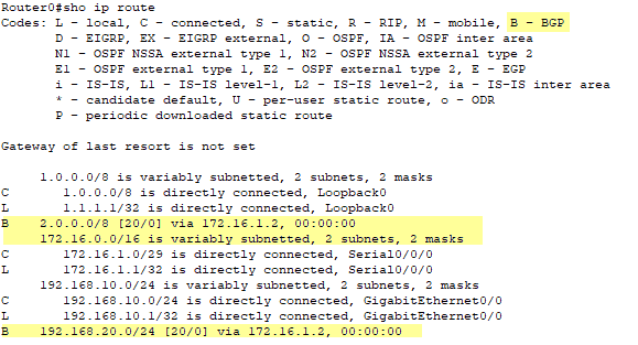
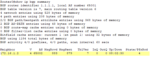
Router0#show ip bgp summary
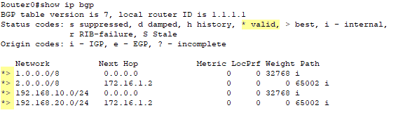
Router0#show ip bgp
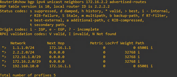
Router0#show bgp ipv4 unicast neighbor 172.16.1.2 advertised-routes
This is another command that is not available in Cisco Packet Tracer as of v8.2. So, here is an example from GNS3.
Ping and Tracert Connectivity Tests
More Notes on BGP
- BGP communicates using TCP port 179
- BGP can form neighbor adjacencies with directly connected routers, which isn't a surprise as other routing protocols do that. But BGP can also form neighbor adjacencies with routers multiple hops away.
Directly Connected BGP Neighbors |
Multihop BGP Neighbors |
| BGP will use the Arp table to locate the Layer 2 address of the peer. | BGP will use routing table information to find the peer's IP address. |
- BGP is a path-vector routing protocol meaning it uses path attributes that are associated with each network path when selecting the best route. This also helps ensure that the path taken is loop free.
- BGP path attributes are defined in RFC 4271 (January 2006 release date).
- RFC 1654 defined BGP and termed it an Inter-Autonomous System routing protocol.
- The 'AS' in the network topology is short for Autonomous System. An Autonomous System is. 'the entire routing domain controlled by a company, ISP, or other organization.
- Inter-Autonomous means that BGP is able to route packets across organizations' routing domains. This makes BGP perfect for the routing of the Internet.
- An organization requests an Autonomous System Number (ASN) from the Internet Service Provider (ISP) or more typically from the Internet Assigned Numbers Authority IANA.
- The ASN is a 16-bit or 32-bit number.
- 32-bit ASN length provides for 4,294,967,295 unique ASNs.
- There are private ASNs that any organization can use. These are similar in concept to the private IP ranges that any organization can use internally listed below.
- Class A 10.0.0.0 - 10.255.255.255
- Class B 172.16.0.0 - 172.31.255.255
- Class C 192.168.0.0 - 192.168.255.255
Private 16-bit ASN Range |
Private 32-bit ASN Range |
| 64,512 - 65,535 | 4,200,000,000 - 4,294,967,294 |
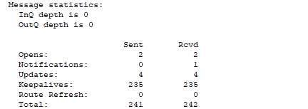
- BGP Peer Communication Message types:
- Open Message
- establishes the BGP adjacency
- Contains - BGP version number, AS number, Hold down timer, other parameters
- Keep Alive
- Ensures the neighbors are still active
- KeepAlive timer set for every 60 seconds by default
- 1/3 of the HoldDown timer, which is 180 seconds by default.
- Update
- These messages are for an update/change to the network.
- NLRI - Network Layer Reachability Information is included in an update message
- Notification
- Error detected
- Neighbor down
- Expiration of HoldDown timer
- BGP Session Reset Requests (clear ip bgp *)
- Error detected
- Open Message
Router0#show ip bgp neighbors
Another Limitation of Cisco Packet Tracer
As of Packet Tracer 8.2 there isn't a command for debug ip bgp which is very odd because there are debug commands for other protocols
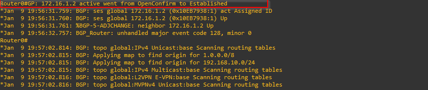
So, for this next section I will be using GNS3 to show the BGP connection handshake. The BGP establishes a TCP session with a neighboring BGP peer or peers. The connection between the peers may report the following states while the connection is established.
- Idle
- Connect
- Active
- OpenSent
- OpenConfirm
- Established
The states can be quite fluid in the ordering as can be seen by and official Cisco diagram showing the states.
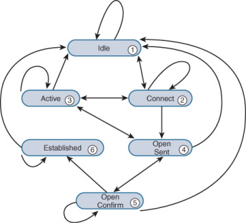
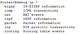
To demo these states in GNS3 I will initiate a debug for the BGP protocol.
Router0#debug ip bgp
Router0#clear ip bgp *
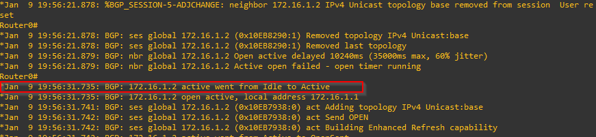
IDLE:
CONNECT:
For the connect phase, I never explicitly saw this reported in the debug logs. I tried two different routers with different Cisco IOS versions and in both cases Idle to Connect never logged. This must be what Cisco was referring to when they said, "The connection between the peers may report the following states while the connection is established."
ACTIVE:
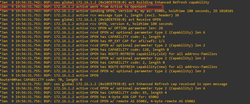
OPENSENT:
OPENCONFIRM:

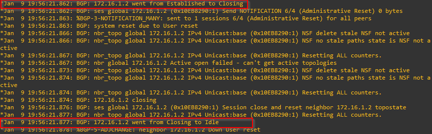
ESTABLISHED:
Now we can check the TCP connectivity.
Router0#show tcp brief

The connection is established. Note that the TCP port on the peer (foreign address) is 179. This peer has the higher IP address and thus manages the connect phase and establishes the port 179 connectivity. The peer with the lower IP will get a randomized port for the connectivity. In this example the randomized port is 57597.
Additional Information about BGP from Cloudflare
Additional Information about BGP Neighbor States and Connectivity from CiscoPress
Cisco Packet Tracer File
BGP Path Attributes
BGP Path Attributes
BGP (Border Gateway protocol is a path vector routing protocol, meaning it uses path attributes to determine the best routing path. There are eight (8) attributes that BGP uses in the determination of that best path.
| Mnemonic | First Letter | BGP Path Attribute |
| We | W | Weight |
| Love | L | Local_pref |
| Oranges | O | Originate |
| As | A | AS_path |
| Oranges | O | Origin type |
| Mean | M | MED (Multiple Exit Discriminator) |
| Pure | P | Paths |
| Refreshment | R | Router-ID |
This is not inclusive of all 13 path attributes but this covers the majority of them. particularly those that we often see used in practice.
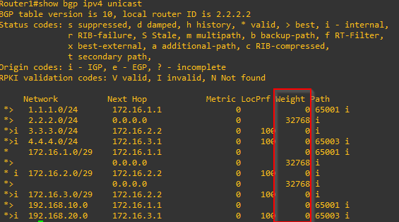
WEIGHT
- Cisco specific parameter
- Local to the router
- Preference: highest weight
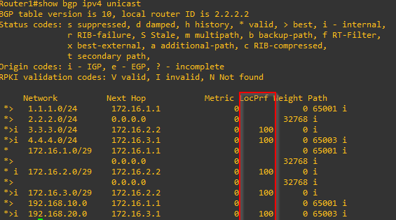
LOCAL PREFERENCE (Local_pref)
This parameter often gets used for route manipulation.
- Default value of 100
- Preference: highest local_pref
ORIGINATE
- How a path was sourced
- Preference: local paths from network or redistribute commands are preferred versus local aggregates via aggregate-address command
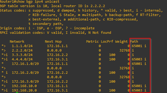
AUTONOMOUS SYSTEM PATH (AS_path)
- The number of autonomous systems in the path
- Preference: shortest AS_path
- It is the number of autonomous systems in the path NOT the number of routers in the path.
ORIGIN TYPE
- Preference: lowest origin type
- IGP
- EGP
- ? Incomplete
MED (Multi-exit Discriminator)
- Optional non-transitive attribute
- A hint to external neighbors about the preferred path into an autonomous system (AS) that has multiple entry points
- Preference: lowest MED
PATHS (eBGP vs iBGP)
- Preference: eBGP over iBGP
| eBGP | iBGP |
| Administrative distance: 20 | Administrative distance: 200 |
ROUTER-ID
- Preference: route from the lowest router ID
Summary of the Attributes
| Mnemonic | First Letter | BGP Path Attribute | Preference |
| We | W | Weight | Higher |
| Love | L | Local_pref | Higher |
| Oranges | O | Originate | Local vs Aggregate |
| As | A | AS_path | Lower |
| Oranges | O | Origin type | IGP vs EGP vs ? |
| Mean | M | MED | Lower |
| Pure | P | Paths | eBGP vs oBGP |
| Refreshment | R | Router-ID | Lower |
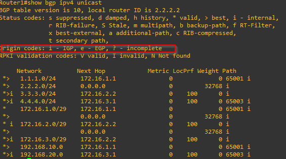
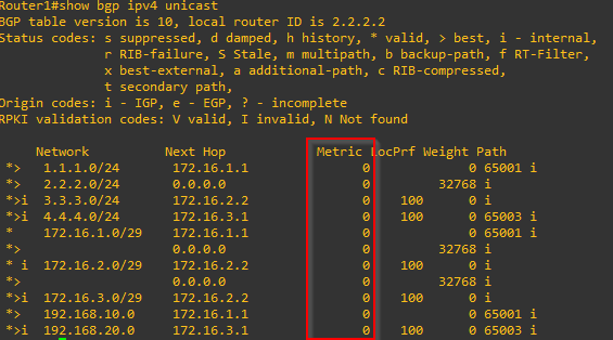
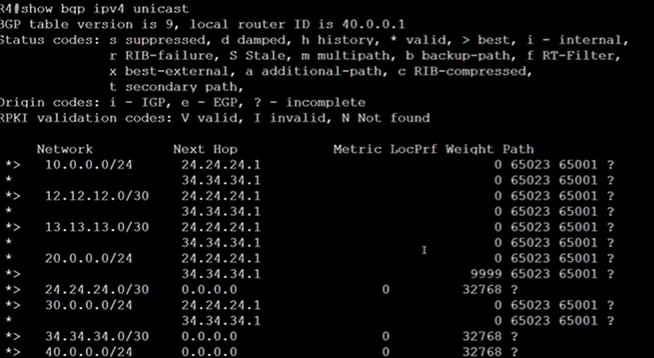
BGP Route Manipulation
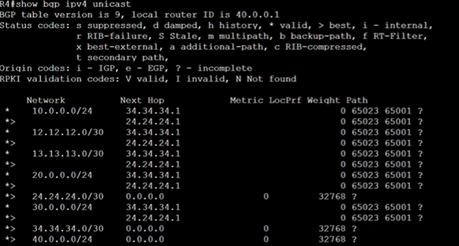
Scenario: Make the preferred path for the 20.0.0.0 network go through another router
R4(config)#ip prefix-list PREF20 permit 20.0.0.0/24
R4(config)#route-map MAP20 permit 10
R4(config-route-map)#match ip address prefix-list PREF20
R4(config-route-map)#set ?

R4(config-route-map)#set weight 999
R4(config-route-map)#exit
R4(config)#route-map MAP20 permit 20
R4(config-route-map)#exit
R4(config)#router bgp 65004
R4(config-router)#neighbor 34.34.34.1 route-map MAP20 in
R4(config-router)#end
R4#clear ip bgp *
Summary of Route Manipulation Steps
| Create a prefix list | Router(config)#ip prefix-list [list name] permit [network IP] |
| Create a route map |
Router(config)#route-map [map name] permit [line #] Router(config-route-map)#set weight [value] |
| Apply the route map to BGP configuration | Router(config-router)#neighbor [neighbor IP address] route-map [map name] [in/out] |
BGP Transitive and Non-transitive Attributes
Transitive Attributes are those BGP attributes that are ALLOWED to be sent to other BGP peers. Non-transitive attributes are NOT allowed to be sent to other peers.
There are four categories of path attributes:
| Well-known mandatory | This attribute MUST exist in the BGP UPDATE. If this attribute is missing a NOTIFICATION error is generated and the session is closed. Must be recognized by all BGP routers and must be included in every update message. Routing information errors occur without this attribute. |
| Well-known discretionary | Can be recognized by all BGP routers; can be included in every update message as needed. |
| Optional transitive | Transitive attribute between ASs. A BGP router not supporting this attribute can still receive routes with this attribute and advertise them to other peers. |
| Optional non-transitive | If a BGP router does not support this attribute, it will not advertise routes with this attribute. |
| BGP Path Attribute | Category |
| Weight | Cisco specific local to router |
| Local_pref | Well-known discretionary |
| AS_path | Well-known mandatory |
| Origin type | Well-known mandatory |
| MED | Optional non-transitive |
Troubleshooting BGP
Cisco IOS Basic MPLS VPN
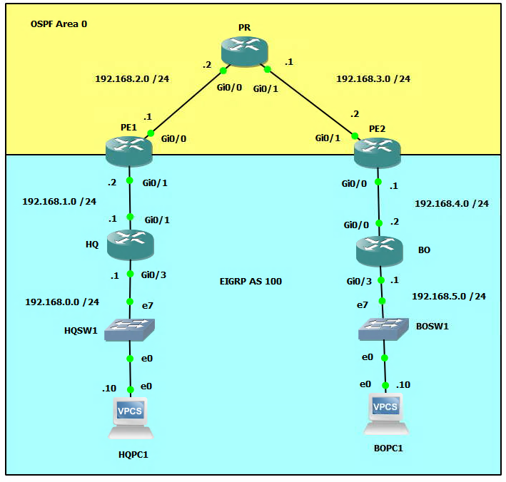
Network Topology
What is MPLS?
Multiprotocol Label Switching (MPLS) is a type of data-carrying technique for high-performance telecommunications networks. It directs data from one network node to the next based on short path labels rather than long network addresses, avoiding complex lookups in a routing table. MPLS can provide better performance, security, and service-level agreements (SLAs) for data traffic. The MPLS protocol is used to create virtual private networks (VPNs) and traffic engineering (TE) networks. It is often used in service provider networks, but can also be used in enterprise networks. MPLS can be used to forward packets using labels, rather than routing them based on their IP addresses. This allows for faster forwarding decisions, because the label can be looked up quickly in a table. MPLS also allows for the creation of virtual links, which can be used to connect different networks together, even if they use different routing protocols.
Multiprotocol Label Switching (MPLS) can be used to create Virtual Private Networks (VPNs). A VPN is a private network that uses a public network (such as the Internet) to connect remote sites or users together. MPLS VPNs use MPLS labels to forward packets between sites, instead of routing them based on their IP addresses. This allows for more efficient and secure communications, as well as the ability to create different virtual networks for different customers or applications.
MPLS VPNs can be configured in different ways, such as:
- MPLS Layer 3 VPNs, which use MPLS to forward packets between sites based on their IP addresses. This allows for the creation of virtual networks that use the same IP addresses as the underlying public network.
- MPLS Layer 2 VPNs, which use MPLS to forward packets between sites based on their MAC addresses. This allows for the creation of virtual networks that use different MAC addresses than the underlying public network.
In both cases, MPLS VPNs use a technique called "VPN label" to identify the different VPNs and forward the packets to the correct destination. MPLS VPNs can also use security features such as encryption, to ensure that the data cannot be intercepted or tampered with while in transit.
MPLS VPNs are widely used by service providers to offer VPN services to their customers. They can also be used in enterprise networks to connect remote sites or branch offices together securely. It's also a good choice for interconnecting multiple sites of a large enterprise as it can provide high performance and better security compared to traditional VPN technologies.
MPLS vs SD-WAN
Multiprotocol Label Switching (MPLS) and Software-Defined WAN (SD-WAN) are both technologies used to connect remote sites or users together, but they have some key differences:
-
MPLS is a type of data-carrying technique that directs data from one network node to the next based on short path labels rather than long network addresses. It is primarily used by service providers to offer VPN services to their customers and can also be used in enterprise networks to connect remote sites or branch offices together.
-
SD-WAN, on the other hand, is a software-based approach to managing WAN connections. It allows for the use of multiple types of connections (such as broadband, cellular, or MPLS) and automatically chooses the best one for each application or user based on factors such as cost, quality, or security. SD-WAN also allows for better visibility and control over network traffic, as well as the ability to easily add or remove sites from the network.
-
MPLS is typically more expensive than SD-WAN, but it offers better security, QoS and SLAs. On the other hand, SD-WAN is more flexible and cost-effective, but it may not provide the same level of security and performance as MPLS.
-
MPLS is a more traditional approach that has been used for more than two decades while SD-WAN is a newer technology that uses software to manage network connections.
-
MPLS is a Layer 3 technology while SD-WAN is a Layer 4-7 technology.
In summary, MPLS is a proven and reliable technology that is well-suited for organizations that require high levels of security and Quality of Service (QoS), while SD-WAN is a cost-effective and flexible option that is well-suited for organizations that need to connect multiple sites or users together in a dynamic way.
Configure the Interface Settings on All Routers and PCs (including Loopback Interfaces on Routers)
HQ>enable
HQ#configure terminal
HQ(config)#interface gigabitEthernet g0/1
HQ(config-if)#ip address 192.168.1.1 255.255.255.0
HQ(config-if)#no shutdown
HQ(config)#interface gigabitEthernet g0/3
HQ(config-if)#ip address 192.168.0.1 255.255.255.0
HQ(config-if)#no shutdown
HQ(config-if)#exit
HQ(config)#interface loopback 0
HQ(config-if)#ip address 1.1.1.1 255.255.255.0
HQ(config-if)#end
PE1>enable
PE1#configure terminal
PE1(config)#interface gigabitEthernet g0/0
PE1(config-if)#ip address 192.168.2.1 255.255.255.0
PE1(config-if)#no shutdown
PE1(config)#interface gigabitEthernet g0/1
PE1(config-if)#ip address 192.168.1.2 255.255.255.0
PE1(config-if)#no shutdown
PE1(config-if)#exit
PE1(config)#interface loopback 0
PE1(config-if)#ip address 2.2.2.2 255.255.255.0
PE1(config-if)#end
PR>enable
PR#configure terminal
PR(config)#interface gigabitEthernet g0/0
PR(config-if)#ip address 192.168.2.2 255.255.255.0
PR(config-if)#no shutdown
PR(config)#interface gigabitEthernet g0/1
PR(config-if)#ip address 192.168.3.1 255.255.255.0
PR(config-if)#no shutdown
PR(config-if)#exit
PR(config)#interface loopback 0
PR(config-if)#ip address 3.3.3.3 255.255.255.0
PR(config-if)#end
PE2>enable
PE2#configure terminal
PE2(config)#interface gigabitEthernet g0/0
PE2(config-if)#ip address 192.168.4.1 255.255.255.0
PE2(config-if)#no shutdown
PE2(config)#interface gigabitEthernet g0/1
PE2(config-if)#ip address 192.168.3.2 255.255.255.0
PE2(config-if)#no shutdown
PE2(config-if)#exit
PE2(config)#interface loopback 0
PE2(config-if)#ip address 4.4.4.4 255.255.255.0
PE2(config-if)#end
BO>enable
BO#configure terminal
BO(config)#interface gigabitEthernet g0/0
BO(config-if)#ip address 192.168.4.2 255.255.255.0
BO(config-if)#no shutdown
BO(config-if)#interface gigabitEthernet g0/3
BO(config-if)#ip address 192.168.5.1 255.255.255.0
BO(config-if)#no shutdown
BO(config-if)#exit
BO(config)#interface loopback 0
BO(config-if)#ip address 5.5.5.5 255.255.255.0
BO(config-if)#end
HQPC1>ip 192.168.0.10/24 192.168.0.1
BOPC1>ip 192.168.5.10/24 192.168.5.1
Setup OSPF Topology for the Provider Edge Routers (PE1 and PE2) and Provider Backbone Router (PR)
PE1>enable
PE1#configure terminal
PE1(config)#router ospf 1
PE1(config-router)#network 192.168.2.0 0.0.0.255 area 0
PE1(config-router)#network 2.2.2.0 0.0.0.255 area 0
PE1(config-router)#passive-interface gigabitEthernet 0/1
PR>enable
PR#configure terminal
PR(config)#router ospf 1
PR(config-router)#network 192.168.2.0 0.0.0.255 area 0
PR(config-router)#network 192.168.3.0 0.0.0.255 area 0
PR(config-router)#network 3.3.3.0 0.0.0.255 area 0
PE2>enable
PE2#configure terminal
PE2(config)#router ospf 1
PE2(config-router)#network 192.168.3.0 0.0.0.255 area 0
PE2(config-router)#network 4.4.4.0 0.0.0.255 area 0
PE2(config-router)#passive-interface gigabitEthernet 0/0
Setup MPLS on the Provider Router Interfaces DO NOT Include the Interfaces Facing the Customer Routers (HQ and BO) on PE1 and PE2
PE1>enable
PE1#configure terminal
PE1(config)#interface gigabitEthernet 0/0
PE1(config-if)#mpls ip
PR>enable
PR#configure terminal
PR(config)#interface gigabitEthernet 0/0
PR(config-if)#mpls ip
PR(config)#interface gigabitEthernet 0/1
PR(config-if)#mpls ip
PE2>enable
PE2#configure terminal
PE2(config)#interface gigabitEthernet 0/1
PE2(config-if)#mpls ip
*You should see a message on the console about the LDP Neighbor switching to a status of UP.
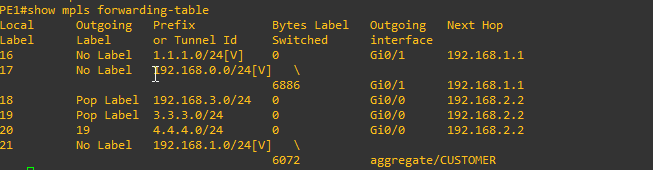
Now let's take a look at the Loopback interfaces by entering the command show mpls forwarding-table.
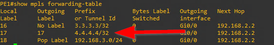
The mask shown on the Loopback interfaces is reporting incorrect so we need to fix this.
PE1(config)#interface loopback 0
PE1(config-if)#ip ospf network point-to-point
PR(config)#interface loopback 0
PR(config-if)#ip ospf network point-to-point
PE2(config)#interface loopback 0
PE2(config-if)#ip ospf network point-to-point
Check the MPLS forwarding-table again to see if the mask is correct on the Loopback
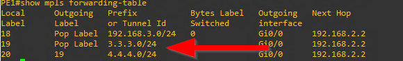
Looks good. the loopback interfaces now have the correct subnet mask of /24
One more thing let's manually force the router-id for mpls to be the Loopback interface IP.
PE1(config)#mpls ldp router-id loopback 0
PR(config)#mpls ldp router-id loopback 0
PE2(config)#mpls ldp router-id loopback 0
Setup Virtual Routing and Forwarding (VRF) for the Customer
PE1>enable
PE1#configure terminal
PE1(config)#ip vrf CUSTOMER
PE1(config-vrf)#rd 100:1
PE1(config-vrf)#route-target both 1:100
PE1(config-vrf)#exit
PE1(config)#interface gigabitEthernet 0/1
PE1(config-if)#ip vrf forwarding CUSTOMER
After setting the vrf on the interface the IP address will be removed and you will have to re-configure it.

PE1(config-if)#ip address 192.168.1.2 255.255.255.0
Now setup the VRF on router PE2 the same way.
PE2>enable
PE2#configure terminal
PE2(config)#ip vrf CUSTOMER
PE2(config-vrf)#rd 100:1
PE2(config-vrf)#route-target both 1:100
PE2(config-vrf)#exit
PE2(config)#interface gigabitEthernet 0/0
PE2(config-if)#ip vrf forwarding CUSTOMER
And don't forget to re-enter the IP configuration for the interface after.
PE2(config-if)ip address 192.168.4.1 255.255.255.0
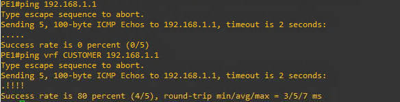
After setting up the VRF you will not be able to ping the interface on the HQ router (192.168.1.1). This is because just using a regular ping without designating the VRF will use the global routing table instead of the virtual routing table for the CUSTOMER VRF. Instead, you have to designate the VRF in the ping command as follows ping vrf CUSTOMER 192.168.1.1
Configure Dynamic Routing Protocols
EIGRP
HQ>enable
HQ#configure terminal
HQ(config)#router eigrp 100
HQ(config-router)#network 192.168.0.0
HQ(config-router)#network 192.168.1.0
HQ(config-router)#network 1.1.1.0
HQ(config-router)#no auto-summary
BO>enable
BO#configure terminal
BO(config)#router eigrp 100
BO(config-router)#network 192.168.4.0
BO(config-router)#network 192.168.5.0
BO(config-router)#network 5.5.5.0
BO(config-router)#no auto-summary
PE1>enable
PE1#configure terminal
PE1(config)#router eigrp1
PE1(config-router)#address-family ipv4 vrf CUSTOMER
PE1(config-router-af)#autonomous-system 100
PE1(config-router-af)#network 192.168.1.0
PE1(config-router-af)#no auto-summary
You should see the EIGRP adjacency message popup

PE2>enable
PE2#configure terminal
PE2(config)#router eigrp1
PE2(config-router)#address-family ipv4 vrf CUSTOMER
PE2(config-router-af)#autonomous-system 100
PE2(config-router-af)#network 192.168.4.0
PE2(config-router-af)#no auto-summary
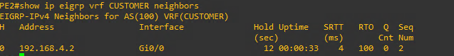
In order to show the EIGRP neighbors from the Provider Edge Routers (PE1 and PE2) keep in mind you have to include the vrf in the command show ip eigrp vrf CUSTOMER neighbors.
We can also check the routing tables from the Provider routers, but again remember to include the correct VRF designation. show ip route vrf CUSTOMER
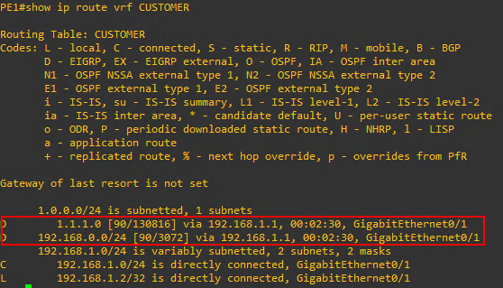
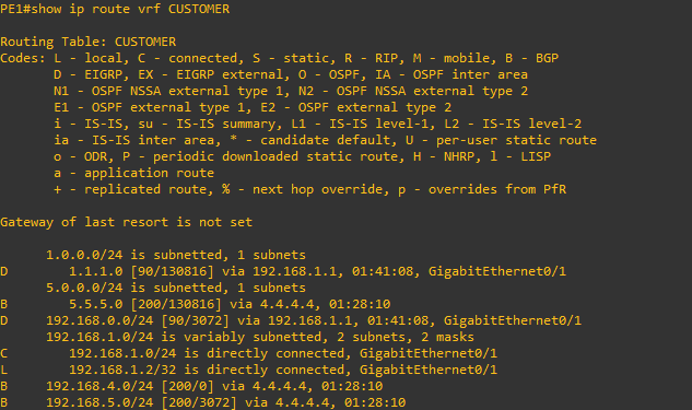
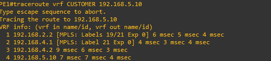
As can be seen above the PE1 Provide Edge Router has learned about the Loopback interface IP of the HQ router as well as the LAN network of 192.168.0.0 And notice that I can ping HQPC1 from the gigabitEthernet 0/1 interface of PE1 but not gigabitEthernet 0/0
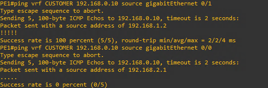
This is as expected because the 0/1 interface is participating in the VRF and knows about the virtual routing table pointing to HQ while the 0/0 interface is not part of the VRF.
iBGP (Internal)
PE1>enable
PE1#configure terminal
PE1(config)#router bgp 1
PE1(config-router)#neighbor 4.4.4.4 remote-as 1
PE1(config-router)#neighbor 4.4.4.4 update-source loopback 0
PE2>enable
PE2#configure terminal
PE2(config)#router bgp 1
PE2(config-router)#neighbor 2.2.2.2 remote-as 1
PE2(config-router)#neighbor 2.2.2.2 update-source loopback 0
You should see the BGP neighbor messages on PE1 and PE2 like below.


Now that we have BGP routing configured we still need to configure the address family and ensure that we are sending communities. In Cisco BGP (Border Gateway Protocol) configuration, the "send-community" command is used to configure the sending of community attributes to other BGP peers. Community attributes are used to group routes together and apply a common set of policies to them. The "send-community" command can be used to specify whether or not to send the standard, extended, or both types of community attributes to BGP peers. The command can also be used to specify whether or not to send the community attributes in both the outbound and inbound directions.
PE1(config)#router bgp 1
PE1(config-router)#address-family vpnv4
PE1(config-router-af)#neighbor 4.4.4.4 activate
PE1(config-router-af)#neighbor 4.4.4.4 send-community both
PE2(config)#router bgp 1
PE2(config-router)#address-family vpnv4
PE2(config-router-af)#neighbor 2.2.2.2 activate
PE2(config-router-af)#neighbor 2.2.2.2 send-community both
Redistribute Protocols
BGP into EIGRP
PE1#configure terminal
PE1(config)#router eigrp 1
PE1(config-router)#address-family ipv4 vrf CUSTOMER
PE1(config-router-af)#redistribute bgp 1 metric 1500 4000 200 10 1500
PE2#configure terminal
PE2(config)#router eigrp 1
PE2(config-router)#address-family ipv4 vrf CUSTOMER
PE2(config-router-af)#redistribute bgp 1 metric 1500 4000 200 10 1500
EIGRP into BGP
PE1#configure terminal
PE1(config)#router bgp 1
PE1(config-router)#address-family ipv4 vrf CUSTOMER
PE1(config-router-af)#redistribute eigrp 100
PE2#configure terminal
PE2(config)#router bgp 1
PE2(config-router)#address-family ipv4 vrf CUSTOMER
PE2(config-router-af)#redistribute eigrp 100
Verify Configuration
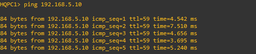
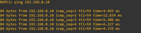
HQPC1>ping 192.168.5.10
BOPC1>ping 192.168.0.10
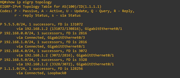
HQ# show ip eigrp topology
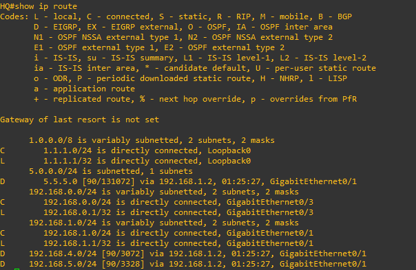
HQ#show ip route
PE1#show ip vrf

PE1#show ip vrf interfaces

PE1#show ip route vrf CUSTOMER
PE1#traceroute vrf CUSTOMER 192.168.5.10
PE1#show mpls interfaces

PE1#show mpls forwarding-table
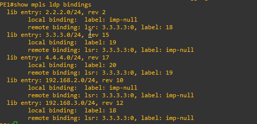
PE1#show mpls ldp bindings
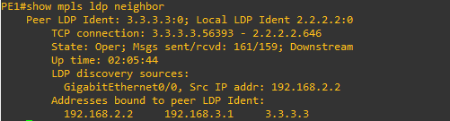
PE1#show mpls ldp neighbor
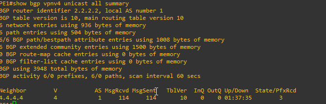
PE1#show bgp vpnv4 unicast all summary
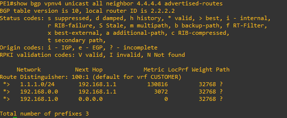
PE1#show bgp vpnv4 unicast all neighbor 4.4.4.4 advertised-routes
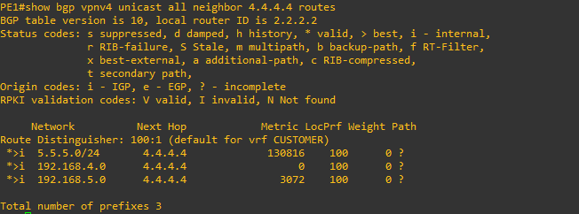
PE1#show bgp vpnv4 unicast all neighbor 4.4.4.4 routes
Reference for Commands
GNS3 File
Cisco IOS Configure Router as DHCP Server
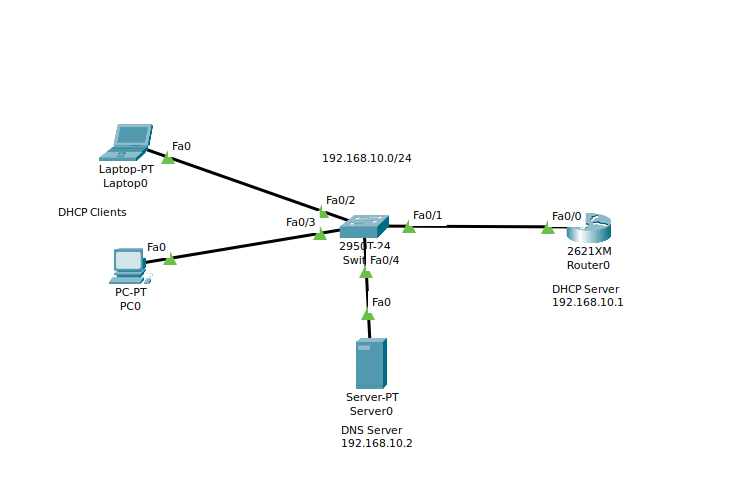
Network Lab Topology
Router0 Configuration Commands
Router0>enable
Router0#configure terminal
Router0(config)# interface fastEthernet 0/0
Router0(config-if)#ip address 192.168.10.1 255.255.255.0
Router0(config-if)#no shutdown
Router0(config-if)#exit
Router0(config)#service dhcp
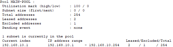
Router0(config)#ip dhcp pool MAIN-POOL
Router0(dhcp-config)#network 192.168.10.0 255.255.255.0
Router0(dhcp-config)#default-router 192.168.10.1
Router0(dhcp-config)#dns-server 192.168.10.2
Router0(dhcp-config)#exit
Router0(config)#ip dhcp excluded-address 192.168.10.1 192.168.10.10
Cisco Packet Tracer File
Cisco IOS Configure DHCP Relay with IP Helper Address
Network Topology

Router1 Configuration Commands
Router1>enable
Router1#configure terminal
Router1(config)# interface fastEthernet 0/0
Router1(config-if)#ip address 172.16.1.1 255.255.255.0
Router1(config-if)#no shutdown
Router1(config-if)#exit
Router1(config)#service dhcp
Router1(config)#ip dhcp pool MAIN-POOL
Router1(dhcp-config)#network 192.168.10.0 255.255.255.0
Router1(dhcp-config)#default-router 192.168.10.1
Router1(dhcp-config)#dns-server 192.168.10.2
Router1(dhcp-config)#exit
Router1(config)#ip dhcp excluded-address 192.168.10.1 192.168.10.10
Router1(config)#ip route 192.168.10.0 255.255.255.0 172.16.1.2
Router0 Configuration Commands
Router0>enable
Router0#configure terminal
Router0(config)# interface fastEthernet 0/1
Router0(config-if)#ip address 172.16.1.2 255.255.255.0
Router0(config-if)#no shutdown
Router0(config)# interface fastEthernet 0/0
Router0(config-if)#ip address 192.168.10.1 255.255.255.0
Router0(config-if)#ip helper-address 172.16.1.1
Router0(config-if)#no shutdown
Router1 DHCP Commands
Router1>enable
Router1#show ip dhcp pool MAIN-POOL
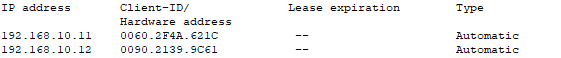
Router1#show ip dhcp binding
Cisco Packet Tracer File
Cisco IOS Configure Router as DNS Server
Network Topology
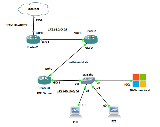
To create this topology, I used GNS3 instead of Cisco Packet Tracer because Packet Tracer routers do not simulate the "ip dns server" command. In the above network Router0 is being configured as a DNS server. Through the configuration of Router0 I wanted to not only demonstrate the ability for the router to resolve local hosts on the network, but I also wanted to show how DNS resolution that Router0 was unable to do could be forwarded to a real DNS server (1.1.1.1) on the Internet. In this way Router0 has been configured to forward unknown requests to the Cloudflare and APNIC's DNS server at 1.1.1.1. I also decided to use a real Windows 2016 Server appliance in the topology. I could have just as easily used another VPCS QEMU device, but it gave me an opportunity to revisit GNS3 Windows appliances. Also, it is not the best practice to use a networking router as the DNS server, but it can be done as this shows.
Router0 Configuration Commands
Router0>enable
Router0#configure terminal
Router0(config)# interface gigabitEthernet 0/0
Router0(config-if)#ip address 192.168.10.1 255.255.255.0
Router0(config-if)#no shutdown
Router0(config-if)#interface gigabitEthernet 0/1
Router0(config-if)#ip address 172.16.1.1 255.255.255.248
Router0(config-if)#no shutdown
Router0(config-if)#exit
Router0(config)#ip dns server
Router0(config)#ip domain-name local
Router0(config)#ip name-server 1.1.1.1
Router0(config)# ip host fileserver.local 192.168.10.2
Router0(config)# ip host pc1.local 192.168.10.3
Router0(config)# ip host pc2.local 192.168.10.4
Router0(config)# ip host router0.local 192.168.10.1
Router0(config)# ip host router1.local 172.16.1.2
Router0(config)# ip host router2.local 172.16.2.1
Router0(config)# ip default-network 192.168.2.0
Router0(config)# router ospf 1
Router0(config-router)# network 172.16.1.0 0.0.0.7 area 0
Router0(config-router)# network 192.168.10.0 0.0.0.255 area 0
Router1 Configuration Commands
Router1>enable
Router1#configure terminal
Router1(config)# interface gigabitEthernet 0/0
Router1(config-if)#ip address 172.16.1.2 255.255.255.248
Router1(config-if)#no shutdown
Router1(config-if)#interface gigabitEthernet 0/1
Router1(config-if)#ip address 172.16.2.2 255.255.255.248
Router1(config-if)#no shutdown
Router1(config-if)#exit
Router1(config)#ip name-server 172.16.1.1
Router1(config)# ip default-network 192.168.2.0
Router1(config)# router ospf 1
Router1(config-router)# network 172.16.1.0 0.0.0.7 area 0
Router1(config-router)# network 172.16.2.0 0.0.0.7 area 0
Router2 Configuration Commands
Router2>enable
Router2#configure terminal
Router2(config)# interface gigabitEthernet 0/0
Router2(config-if)#ip address dhcp
Router2(config-if)#no shutdown
Router2(config-if)#ip nat outside
Router2(config-if)#interface gigabitEthernet 0/1
Router2(config-if)#ip address 172.16.2.1 255.255.255.248
Router2(config-if)#no shutdown
Router2(config-if)#ip nat inside
Router2(config-if)#exit
Router2(config)#ip nat inside source list 1 interface gigabitEthernet0/0 overload
Router2(config)#access-list 1 permit any
Router2(config)# router ospf 1
Router2(config-router)# network 192.168.2.0 0.0.0.255 area 0
Router2(config-router)# network 172.16.2.0 0.0.0.7 area 0
The configuration of nat on Router2 is so that the network can communicate to the connected network and then to the Internet through the GNS3 cloud object. I did this to demonstrate the DNS forwarder on Router0 to 1.1.1.1 Also, the IP address on gigabitEthernet 0/0 is set for DHCP as it is getting an address from my network DHCP server. You could also make this a static address if desired. If you do set a static IP address, remember to configure a gateway of last resort. The DHCP setting configures that for the interface automatically.
Check DNS (a few ping examples)
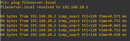
PC1>ping fileserver.local
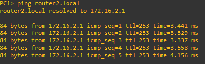
PC1>ping router2.local
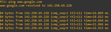
PC1>ping www.google.com
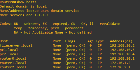
Check the configured DNS Hosts on Router0
Router0#show hosts
GNS3 File
net11 cisco router dns server.gns3
Cisco IOS VRF-Lite
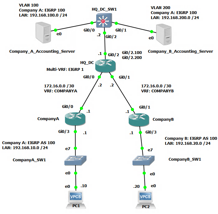
Network Topology
Difference Between VRF and VRF-Lite Explained
VRF (Virtual Routing and Forwarding) and VRF-Lite (also known as Multi-VRF CE or MVPN) are both technologies used in networking to create multiple virtual routing and forwarding instances within a single physical router.
The main difference between the two is in the scope of their implementation. VRF is typically used in service provider networks, where it allows for multiple customers to share the same physical infrastructure while still maintaining separate and isolated routing domains. VRF-Lite, on the other hand, is typically used in enterprise networks, where it allows for multiple logical networks to be created within a single physical network infrastructure.
In summary, VRF is used for service provider networks, and VRF-Lite is used for enterprise networks.
Scenario
Company A has just completed an M&A process and acquired Company B. As part of the post acquisition integration process the decision was made to move Company B's IT equipment into the datacenter hosting facility used by Company A. However, there are some critical elements in Company B such as network addressing and routing that cannot be immediately changed and must stay in place. It is a must, at least in the near to medium term to keep the Company B Accounting and Finance systems separate and secured from other parts of the overall company network while still providing the necessary access to authorized users and their computers. Additionally it was discovered that Company B uses the same network subnet as Company B for the uplink to the Company B main router. This has further complicated the plan to consolidate the topology to just one main router (HQ_DC). However, you have a plan to use VRF-Lite and some VLAN architecture to solve these challenges.
Configuration
These configuration steps will demonstrate the configuration for both Company A and Company B for completeness. Obviously in the scenario much of Company A's infrastructure configuration would already be done.
CompanyA Router
CompanyA>enable
CompanyA#configure terminal
CompanyA(config)#interface gigabitEthernet 0/3
CompanyA(config-if)#ip address 192.168.10.1 255.255.255.0
CompanyA(config-if)#no shutdown
CompanyA(config-if)#interface gigabitEthernet 0/0
CompanyA(config-if)#ip address 172.16.0.1 255.255.255.252
CompanyA(config-if)#no shutdown
CompanyA(config-if)#exit
CompanyA(config)#router eigrp 100
CompanyA(config-router)#network 0.0.0.0 0.0.0.0
CompanyA(config-router)#no auto-summary
CompanyA(config-router)#end
CompanyB Router
CompanyB>enable
CompanyB#configure terminal
CompanyA(config)#interface gigabitEthernet 0/3
CompanyA(config-if)#ip address 192.168.20.1 255.255.255.0
CompanyA(config-if)#no shutdown
CompanyA(config-if)#interface gigabitEthernet 0/0
CompanyA(config-if)#ip address 172.16.0.1 255.255.255.252
CompanyA(config-if)#no shutdown
CompanyA(config-if)#exit
CompanyA(config)#router eigrp 100
CompanyA(config-router)#network 0.0.0.0 0.0.0.0
CompanyA(config-router)#no auto-summary
CompanyA(config-router)#end
HQ_DC Router
HQ_DC>enable
HQ_DC#configure terminal
HQ_DC(config)#ip vrf COMPANYA
HQ_DC(config-vrf)#exit
HQ_DC(config)#ip vrf COMPANYB
HQ_DC(config-vrf)#exit
HQ_DC(config)#interface gigabitEthernet 0/0
HQ_DC(config-if)#ip address 172.16.0.2 255.255.255.252
HQ_DC(config-if)#description COMPANYA main circuit
HQ_DC(config-if)#ip vrf forwarding COMPANYA
HQ_DC(config-if)#exit
HQ_DC(config)#interface gigabitEthernet 0/1
HQ_DC(config-if)#ip address 172.16.0.2 255.255.255.252
HQ_DC(config-if)#description COMPANYB main circuit
HQ_DC(config-if)#ip vrf forwarding COMPANYB
HQ_DC(config-if)#exit
HQ_DC(config)#interface gigabitEthernet 0/2
HQ_DC(config-if)#no shutdown
HQ_DC(config-if)#interface gigabitEthernet 0/2.100
HQ_DC(config-subif)#description COMPANYA dc circuit
HQ_DC(config-subif)#encapsulation dot1q 100
HQ_DC(config-subif)#ip vrf forwarding COMPANYA
HQ_DC(config-subif)#ip address 192.168.100.1 255.255.255.0
HQ_DC(config-if)#interface gigabitEthernet 0/2.200
HQ_DC(config-subif)#description COMPANYB dc circuit
HQ_DC(config-subif)#encapsulation dot1q 200
HQ_DC(config-subif)#ip vrf forwarding COMPANYB
HQ_DC(config-subif)#ip address 192.168.200.1 255.255.255.0
HQ_DC(config-subif)#exit
HQ_DC(config)#router eigrp 1
HQ_DC(config-router)#address-family ipv4 vrf COMPANYA
HQ_DC(config-router-af)#network 0.0.0.0 0.0.0.0
HQ_DC(config-router-af)#autonomous-system 100
HQ_DC(config-router-af)#no auto-summary
HQ_DC(config-router-af)#exit
HQ_DC(config-router)#address-family ipv4 vrf COMPANYB
HQ_DC(config-router-af)#network 0.0.0.0 0.0.0.0
HQ_DC(config-router-af)#autonomous-system 100
HQ_DC(config-router-af)#no auto-summary
HQ_DC_SW1 Switch
HQ_DC_SW1>enable
HQ_DC_SW1#configure terminal
HQ_DC_SW1(config)#vlan 100
HQ_DC_SW1(config-vlan)#name COMPANYA
HQ_DC_SW1)config-vlan)#exit
HQ_DC_SW1(config)#vlan 200
HQ_DC_SW1(config-vlan)#name COMPANYB
HQ_DC_SW1)config-vlan)#exit
HQ_DC_SW1(config)#interface gigabitEthernet 0/2
HQ_DC_SW1(config-if)#switchport trunk encapsulation dot1q
HQ_DC_SW1(config-if)#switchport mode trunk
HQ_DC_SW1(config-if)#switchport trunk allowed vlan 100,200
HQ_DC_SW1(config-if)#interface gigabitEthernet 0/0
HQ_DC_SW1(config-if)#switchport access vlan 100
HQ_DC_SW1(config-if)#interface gigabitEthernet 0/1
HQ_DC_SW1(config-if)#switchport access vlan 200
HQ_DC_SW1(config-if)#exit
HQ_DC_SW1(config)#interface vlan 100
HQ_DC_SW1(config-if)#ip address 192.168.100.2 255.255.255.0
HQ_DC_SW1(config-if)#exit
HQ_DC_SW1(config)#interface vlan 200
HQ_DC_SW1(config-if)#ip address 192.168.200.2 255.255.255.0
PCs and Servers
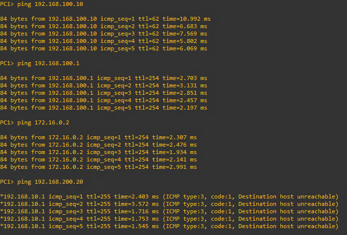
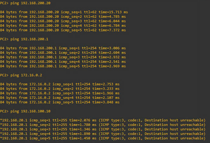
PC1>ip 192.168.10.10/24 192.168.10.1
PC2>ip 192.168.20.20/24 192.168.20.1
COMPA_ACCT> ip address 192.168.100.10/24 192.168.100.1
COMPB_ACCT> ip address 192.168.200.20/24 192.168.200.1
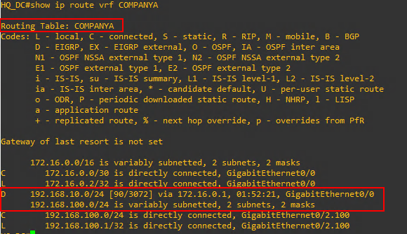
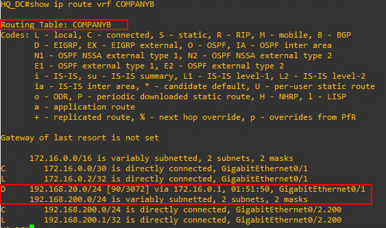
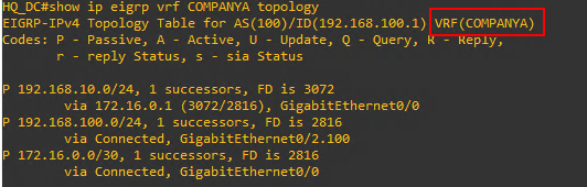
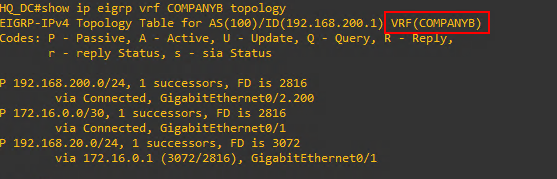
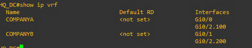
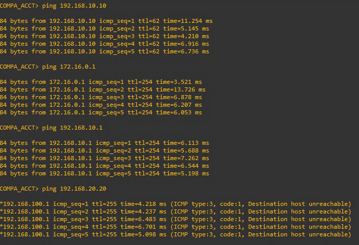
Test and Verify Connectivity and Configuration
GNS3 File
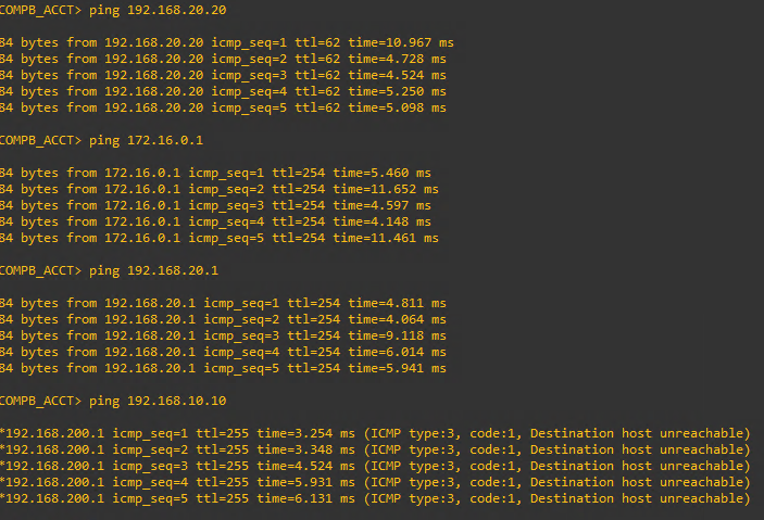
Cisco IOS Site to Site VPN (Router)
Network Topology
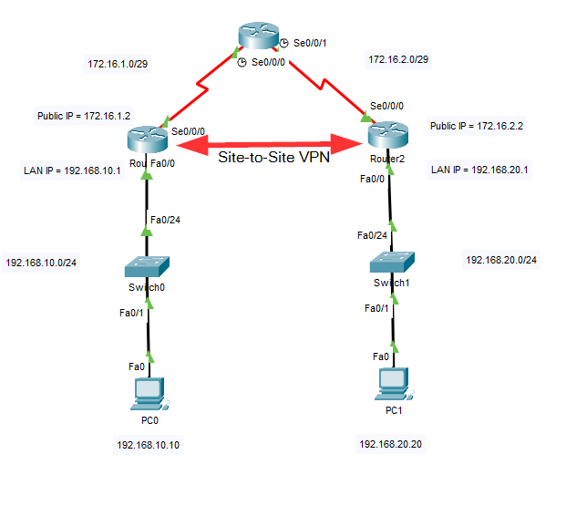
In this network configuration a site-to-site VPN between Router1 and Router2 across the link through Router0.
First let's set up the IP and routing information on all three routers as well as the two PCs.
Router0 IP and Routing Configuration Commands
Router0>enable
Router0#configure terminal
Router0(config)# interface serial 0/0/0
Router0(config-if)#ip address 172.16.1.1 255.255.255.248
Router0(config-if)#no shutdown
Router0(config-if)#interface serial 0/0/1
Router0(config-if)#ip address 172.16.2.1 255.255.255.248
Router0(config-if)#no shutdown
Router0(config-if)#exit
Router0(config)#ip route 192.168.10.0 255.255.255.0 172.16.1.2
Router0(config)#ip route 192.168.20.0 255.255.255.0 172.16.2.2
Router1 IP and Routing Configuration Commands
Router1>enable
Router1#configure terminal
Router1(config)# interface serial 0/0/0
Router1(config-if)#ip address 172.16.1.2 255.255.255.248
Router1(config-if)#no shutdown
Router1(config-if)#interface fastEthernet 0/0
Router1(config-if)#ip address 192.168.10.1 255.255.255.0
Router1(config-if)#no shutdown
Router1(config-if)#exit
Router1(config)#ip route 0.0.0.0 0.0.0.0 172.16.1.1
Router2 IP and Routing Configuration Commands
Router1>enable
Router1#configure terminal
Router1(config)# interface serial 0/0/0
Router1(config-if)#ip address 172.16.2.2 255.255.255.248
Router1(config-if)#no shutdown
Router1(config-if)#interface fastEthernet 0/0
Router1(config-if)#ip address 192.168.20.1 255.255.255.0
Router1(config-if)#no shutdown
Router1(config-if)#exit
Router1(config)#ip route 0.0.0.0 0.0.0.0 172.16.2.1
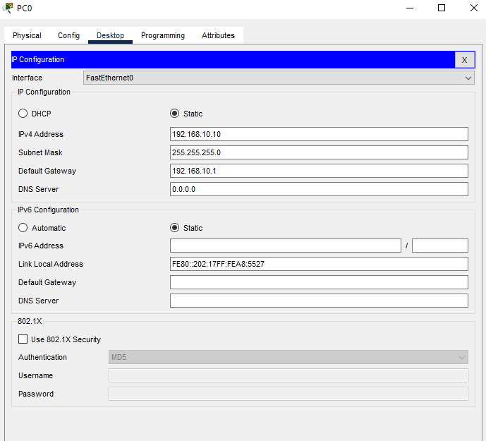
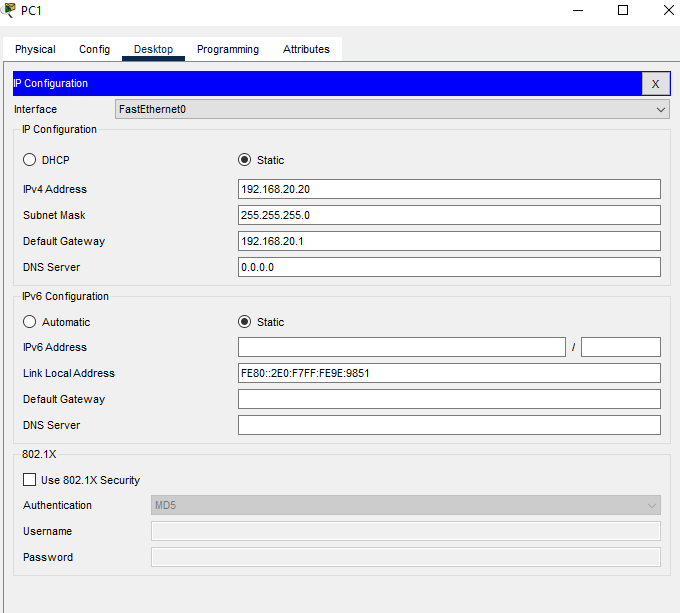
PC Computers IP Configuration
Now that all the routers and PCs have their IP addressing and routing information configured it is time to move on the the specific configuration for enabling the Site-to-Site VPN. This process can be divided into four phases.
Phase 1 - The Key Exchange Setup
| Phase 1 Commands | Notes |
| crypto isakmp enable | |
| crypto isakmp policy 10 | The number can be any number between 1 and 10,000. It identifies the priority of the policy. |
| encryption aes | this could be 3des but aes is more robust. |
| hash sha | sha = secure hash algorithm. md5 could be used but sha is more robust. |
| group 1 | Specifies the Diffie-Hellman group identifier, which the two IPsec peers use to derive a shared secret without transmitting it to each other. Group 1 is 768-bit |
| lifetime 3600 | Specifies the Security Association (SA) lifetime. The default is 86,400 seconds or 24 hours. As a general rule, a shorter lifetime provides more secure ISAKMP negotiations (up to a point). However, with shorter lifetimes, the security appliance sets up future IPsec SAs more quickly. |
| authentication pre-share | |
| crypto isakmp key ciscokey123 address 172.16.2.2 | The italicized text is just a text string that has to match on both sides of the connection. The IP address is the public IP address of our peer on the other side of the VPN connection. |
Phase 2 - Encrypting the Tunnel
| Phase 2 Commands | Notes |
| crypto ipsec transform-set vpnset esp-aes esp-sha-hmac | The italicized text is the set name and can be changed. This could be esp-3des and esp-md5-hmac |
| crypto map vpnset 10 ipsec-isakmp | The number is any number between 1 and 65,535 that identifies the sequence to insert into the crypto map. |
| set transform-set vpnset | |
| match address 100 | Match the addresses in the access control list coming up. This will identify the inside-to-inside traffic flow. |
| set peer 172.16.2.2 | This is the other router's outside interface. |
Phase 3 - Applying the Crypto Map to the Outside Router Interface
| Phase 3 Commands | Notes |
| int s0/0/0 | Whatever the outside interface of the router is (f0/0, g0/2, etc.) |
| crypto map vpnset |
Phase 4 - Creating an Access List to Identify the Traffic Flow (inside to inside LAN traffic)
| Phase 4 Commands | Notes |
| access-list 100 permit ip 192.168.10.0 0.0.0.255 192.168.20.0 0.0.0.255 | These are the inside addresses of both routers. |
Let's start with Router1
Router1 VPN Configuration Commands
Router1>enable
Router1#configure terminal
Router1(config)#crypto isakmp enable
Router1(config)#crypto isakmp policy 10
Router1(config-isakmp)#encryption aes
Router1(config-isakmp)#hash sha
Router1(config-isakmp)#group 1
Router1(config-isakmp)#lifetime 3600
Router1(config-isakmp)#authentication pre-share
Router1(config-isakmp)#exit
Router1(config)#crypto isakmp key ciscokey123 address 172.16.2.2
Router1(config)#crypto map vpnset 10 ipsec-isakmp
Router1(config-crypto-map)#set transform-set vpnset
Router1(config-crypto-map)#match address 100
Router1(config-crypto-map)#set peer 172.16.2.2
Router1(config-crypto-map)#exit
Router1(config)#int serial 0/0/0
Router1(config-if)#crypto map vpnset
Router1(config-if)#exit
Router1(config)#access-list 100 permit ip 192.168.10.0 0.0.0.255 192.168.20.0 0.0.0.255
Router2 VPN Configuration Commands
Router2>enable
Router2#configure terminal
Router2(config)#crypto isakmp enable
Router2(config)#crypto isakmp policy 10
Router2(config-isakmp)#encryption aes
Router2(config-isakmp)#hash sha
Router2(config-isakmp)#group 1
Router2(config-isakmp)#lifetime 3600
Router2(config-isakmp)#authentication pre-share
Router2(config-isakmp)#exit
Router2(config)#crypto isakmp key ciscokey123 address 172.16.1.2
Router2(config)#crypto map vpnset 10 ipsec-isakmp
Router2(config-crypto-map)#set transform-set vpnset
Router2(config-crypto-map)#match address 100
Router2(config-crypto-map)#set peer 172.16.1.2
Router2(config-crypto-map)#exit
Router2(config)#int serial 0/0/0
Router2(config-if)#crypto map vpnset
Router2(config-if)#exit
Router2(config)#access-list 100 permit ip 192.168.20.0 0.0.0.255 192.168.10.0 0.0.0.255
Check Status of VPN
Check the status of the Internet Security Association Management Protocol (ISAKMP) Security Associations (SAs) built between the peers.
Router1#show crypto isakmp sa
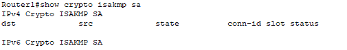
If you run the command right after establishing the VPN you might see a very blank status screen. You can wait for connections to start establishing across the VPN or you can simply do a ping across the VPN. Then when you run the command again you should see a more informative status like this.
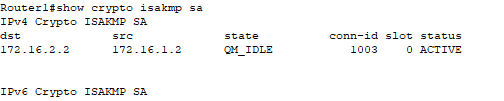
You can see from the output above the destination's (Router2) IP address and the source (Router1). And most importantly the status shows that the security association (link) is ACTIVE.
Check the Internet Security Association Management Protocol (ISAKMP) Policy
Router1#show crypto isakmp policy
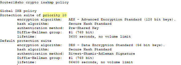
As you can see our new ISAKMP policy is at a higher priority than the default protection suite policy. This output shows the priority, the encryption type (AES), the authentication method (pre-shared), the Diffie-Hellman group (1), and the lifetime (3600). These are all the values we set in the configuration.
Check the Crypto Map Settings
Router1#show crypto map
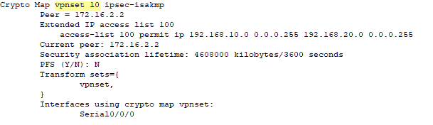
A wealth of information about the configured cryto map including the name and sequence number. The configured peer is visible. The access-list is present as well as the interface that the map is assigned.
Check the IPSEC Security Association
Router1#show crypto ipsec sa
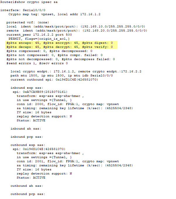
There is a lot of information given in this command but probably the most valuable is the highlighted area above showing that encapsulation and decapsulation is taking place across the VPN. Additionally, you can see status for inbound and outbound tunnel and the configured encryption algorithms.
Check Ping from PC0 to PC1 and visa versa
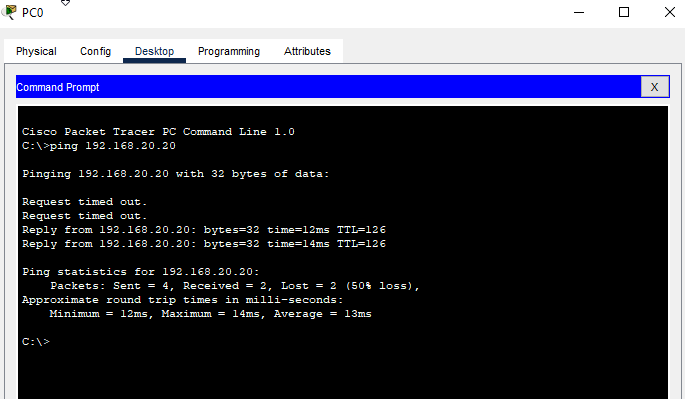
The first ping will most likely lose some packets, but subsequent pings will complete 100%
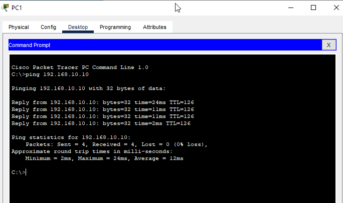
Cisco Packet Tracer File
Cisco ASA 5505 Internet Access
Network Topology
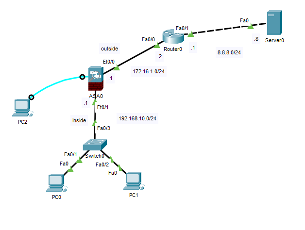
Step 1 - Remove Existing ASA Configuration
In Cisco Packet Tracer the ASA 5505 already starts out with some configuration as show by the show running-config command output below.
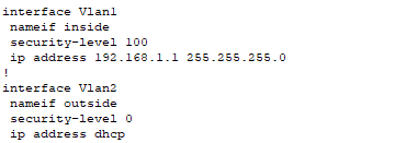
It also has a dhcpd server enabled and partially configured.
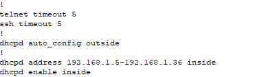
In addition, there are configure vlan interfaces with assigned interfaces.
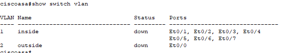
To create our own configuration, we will have to first dismantle the configuration elements that already are in place.
ciscoasa>enable
password:
ciscoasa#configure terminal
ciscoasa(config)#hostname ASA0
ASA0(config)#interface vlan 1
ASA0(config-if)#no ip address
ASA0(config-if)#exit
ASA0(config)#no dhcpd address 192.168.1.5-192.168.1.36 inside
ASA0(config)#end
ASA0#show running-config
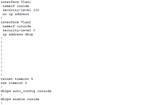
Step 2 - Configure VLAN Interfaces, Assign Ethernet Interfaces to Correct VLANs, and Ensure Correct Security-Levels
ASA0#configure terminal
ASA0(config)#interface vlan 1
ASA0(config-if)#ip address 192.168.10.1 255.255.255.0
ASA0(config-if)#nameif inside
ASA0(config-if)#security-level 100
ASA0(config-if)#no shutdown
ASA0(config-if)#exit
ASA0(config)#interface vlan 2
ASA0(config-if)#ip address 172.16.1.1 255.255.255.0
ASA0(config-if)#nameif outside
ASA0(config-if)#security-level 0
ASA0(config-if)#no shutdown
ASA0(config-if)#exit
ASA0(config)#interface ethernet 0/1
ASA0(config-if)#switchport access vlan 1
ASA0(config-if)#exit
ASA0(config)#interface ethernet 0/0
ASA0(config-if)#switchport access vlan 2
ASA0(config-if)#end
ASA#show running-config
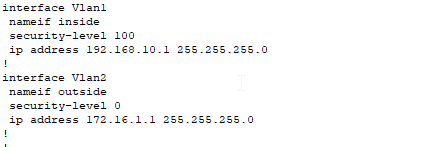
ASA#show switch vlan
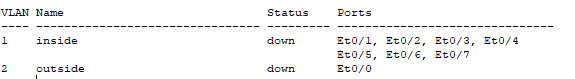
Step 3 - Configure the ISP Router
Now it's time to configure the router. This router (Router0) is like the ISP router on the far side of our connection to the Internet. In this configuration I will be using OSPF to dynamically route the networks of 172.16.1.0/24 and 8.8.8.0/24. You could just as easily use static routes and default gateways or even another dynamic routing protocol. I just chose OSPF.
Router0>enable
Router0#configure terminal
Router0(config)#interface fastEthernet 0/0
Router(config-if)#ip address 172.16.1.2 255.255.255.0
Router(config-if)#no shutdown
Router(config-if)#interface fasEthernet 0/1
Router(config-if)#ip address 8.8.8.1 255.255.255.0
Router0(config-if)#exit
Router0(config)#router ospf 1
Router0(config-router)#network 172.16.1.0 0.0.0.255 area 0
Router0(config-router)#network 8.8.8.0 0.0.0.255 area 0
Router0(config-router)#end
Router0#
Step 4 - Configure DHCP Server on ASA
Next let's configure the dhcp server addressing on the ASA0 firewall. The dhcpd is already enabled we just have to configure the correct addressing to match our internal LAN subnet addressing. Before we configure the ASA through, make sure the PC0 and PC1 are set to obtain their IP addresses via DHCP.
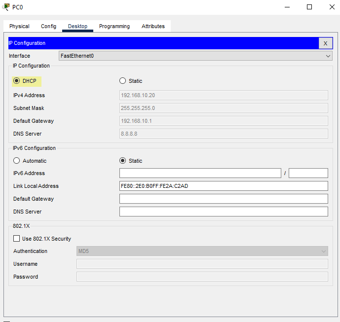
ASA0#configure terminal
ASA0(config)#dhcpd address 192.168.10.20-192.168.10.30 inside
ASA0(config)#dhcpd dns 8.8.8.8 interface inside
ASA0(config)#end
ASA0#show running-config
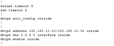
Check PC0 and PC1 IP addresses
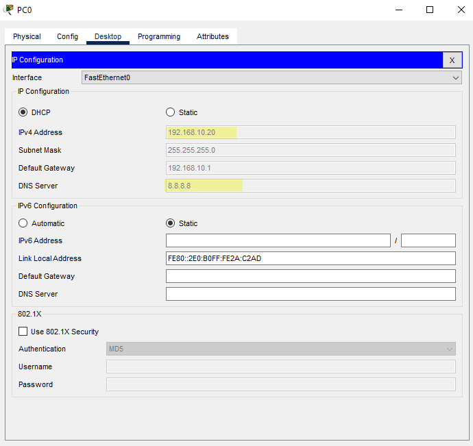
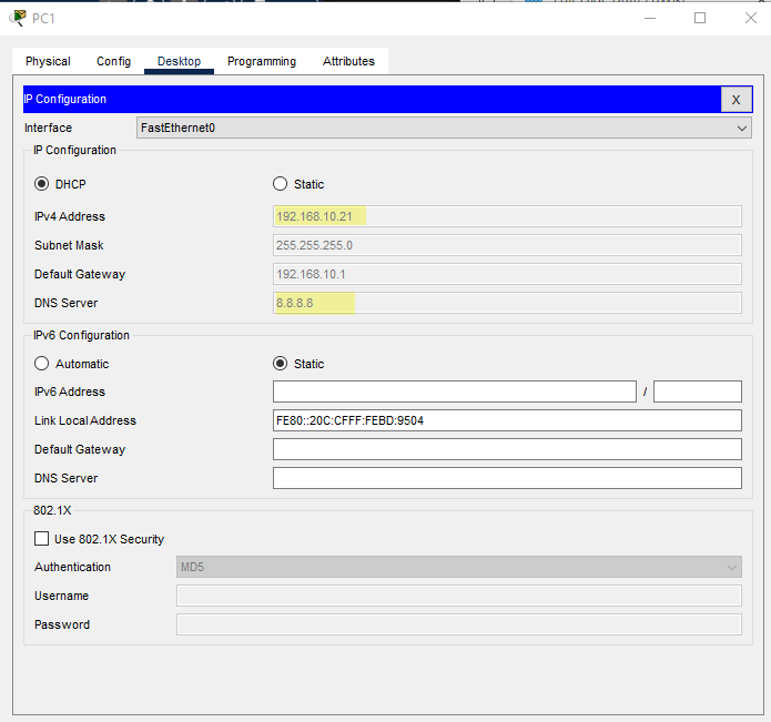
DHCP is working properly.
Step 5 - Configure Default Route on ASA, Create Network Object, and Configure Network Address Translation (NAT)
ASA0#configure terminal
ASA0(config)#route outside 0.0.0.0 0.0.0.0 172.16.1.2
ASA0(config)#object network LAN
ASA0(config-network-object)#subnet 192.168.10.0 255.255.255.0
ASA0(config-network-object)#nat (inside,outside) dynamic interface
ASA0(config-network-object)#exit
ASA0(config)#access-list in_to_internet extended permit tcp any any
ASA0(config)#access-list in_to_internet extended permit icmp any any
ASA0(config)#access-group in_to_internet in interface outside
ASA0(config)#
Now check ping to the server at 8.8.8.8 from PC0 or PC1
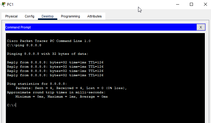
Now we will verity NAT
ASA0#show xlate

Nothing to show so start a continuous ping from PC0 and PC1 ping -t 8.8.8.8 and re-run the show xlate command on the ASA
ASA0#show xlate
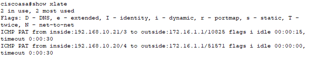
ASA0#show nat
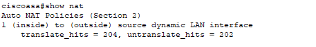
Cisco Packet Trace File
Cisco IOS Private VLANs
Network Topology
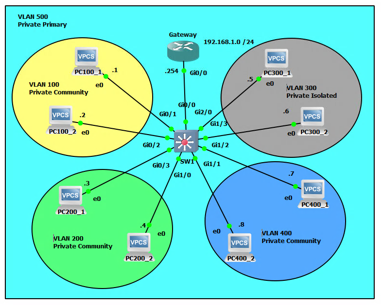
What is a Private VLAN?
A private VLAN, also known as a private LAN, is a VLAN (Virtual Local Area Network) that is used to segment a larger network into smaller, more secure subnets. It is used to isolate different types of traffic or to separate sensitive or confidential information from other network traffic.
A private VLAN typically consists of three types of ports: promiscuous ports, host ports, and community ports. Promiscuous ports can communicate with all other ports in the private VLAN, while host ports can only communicate with promiscuous ports. Community ports can only communicate with other ports in the same community. This allows for a high level of granularity in terms of controlling access and isolating different types of traffic on a network.
Promiscuous ports, isolated ports, and community ports are different types of ports that are used in private VLAN (PVLAN) environments to control access and isolate different types of traffic on a network.
- Promiscuous Ports: These ports can communicate with all other ports in the private VLAN, including host and community ports. They are typically used for gateway or router connections and can be used to access shared resources or provide access to other networks.
- Isolated Ports: These ports can only communicate with the associated promiscuous port and cannot communicate with other isolated or community ports. They are typically used to isolate sensitive or confidential information and prevent it from being accessed by other parts of the network.
- Community Ports: These ports can only communicate with other ports within the same community and not with other communities or promiscuous ports. They are used to create isolated groups within a private VLAN and to control access to shared resources.
In summary, promiscuous ports allow communication with all other ports in the PVLAN, isolated ports are used to isolate sensitive information and prevent it from being accessed by other parts of the network, and community ports are used to create isolated groups within a PVLAN and control access to shared resources.
Private VLANs are often used in enterprise networks, data centers, and service provider environments to segment traffic and provide additional security. They can also be used to isolate guest or IoT traffic, to separate different departments or groups within an organization, or to separate different types of traffic on a network.
What is a Private Isolated VLAN?
A private isolated VLAN is a good solution for keeping sensitive or confidential information separate from other network traffic. It can be used for segmenting a network into secure and non-secure zones, for example, to isolate traffic from a secure server or database from the rest of the network. Additionally, it can be used to create secure zones for specific departments or groups within an organization, or to separate different types of traffic on a network, such as guest or IoT traffic. Some things that Private VLANs can be beneficial for include:
- Segmenting a network into secure and non-secure zones: In this scenario, a private isolated VLAN would be used to separate sensitive or confidential information from other network traffic. This could include separating a secure server or database from the rest of the network, or isolating traffic from a specific department or group that handles sensitive information.
- Isolating guest traffic: In a scenario where guest wireless access is provided, a private isolated VLAN could be used to separate guest traffic from internal network traffic. This would help to prevent guests from accessing sensitive or confidential information on the internal network.
- Isolating IoT traffic: In a scenario where there are a large number of IoT devices connected to a network, a private isolated VLAN could be used to separate IoT traffic from other network traffic. This would help to prevent IoT devices from accessing sensitive or confidential information on the network and also prevent any potential security risks from these devices.
- Isolating different types of traffic: In a scenario where there are multiple types of traffic on a network, such as voice and data traffic, a private isolated VLAN could be used to separate the different types of traffic. This would help to ensure that voice traffic, for example, is prioritized over data traffic, and that there is no interference between the different types of traffic on the network.
Configuration
PCs
PC100_1>ip 192.168.1.1/24 192.168.1.254
PC100_2>ip 192.168.1.2/24 192.168.1.254
PC200_1>ip 192.168.1.3/24 192.168.1.254
PC200_2>ip 192.168.1.4/24 192.168.1.254
PC300_1>ip 192.168.1.5/24 192.168.1.254
PC300_2>ip 192.168.1.6/24 192.168.1.254
PC400_1>ip 192.168.1.7/24 192.168.1.254
PC400_2>ip 192.168.1.8/24 192.168.1.254
Gateway
Gateway>enable
Gateway#configure terminal
Gateway(config)#interface gigabitEthernet 0/0
Gateway((config-if)#ip address 192.168.1.254 255.255.255.0
Gateway(config-if)#no shutdown
SW1
SW1>enable
SW1#configure terminal
SW1(config)#vtp mode transparent
SW1(config)#vlan 100
SW1(config-vlan)#private-vlan community
SW1(config-vlan)#exit
SW1(config)#vlan 200
SW1(config-vlan)#private-vlan community
SW1(config-vlan)#exit
SW1(config)#vlan 300
SW1(config-vlan)#private-vlan isolated
SW1(config-vlan)#exit
SW1(config)#vlan 400
SW1(config-vlan)#private-vlan community
SW1(config-vlan)#exit
SW1(config)#vlan 500
SW1(config-vlan)#private-vlan primary
SW1(config-vlan)#private-vlan association 100,200,300,400
SW1(config-vlan)#exit
SW1(config)#interface gigabitEthernet g0/1
SW1(config-if)#switchport mode private-vlan host
SW1(config-if)#switchport private-vlan host-association 500 100
SW1(config)#interface gigabitEthernet g0/2
SW1(config-if)#switchport mode private-vlan host
SW1(config-if)#switchport private-vlan host-association 500 100
SW1(config)#interface gigabitEthernet g0/3
SW1(config-if)#switchport mode private-vlan host
SW1(config-if)#switchport private-vlan host-association 500 200
SW1(config)#interface gigabitEthernet g1/0
SW1(config-if)#switchport mode private-vlan host
SW1(config-if)#switchport private-vlan host-association 500 200
SW1(config)#interface gigabitEthernet g2/0
SW1(config-if)#switchport mode private-vlan host
SW1(confi-if)#switchport private-vlan host-association 500 300
SW1(config)#interface gigabitEthernet g1/3
SW1(config-if)#switchport mode private-vlan host
SW1(confi-if)#switchport private-vlan host-association 500 300
SW1(config)#interface gigabitEthernet g1/2
SW1(config-if)#switchport mode private-vlan host
SW1(confi-if)#switchport private-vlan host-association 500 400
SW1(config)#interface gigabitEthernet g1/1
SW1(config-if)#switchport mode private-vlan host
SW1(confi-if)#switchport private-vlan host-association 500 400
SW1(config)#interface gigabitEthernet g0/0
SW1(config-if)#switchport mode private-vlan promiscuous
SW1(confi-if)#switchport private-vlan mapping 500 100,200,300,400
SW1(confi-if)#end
Illustrated Scenarios
Intra-community VLAN Communication will be Successful.
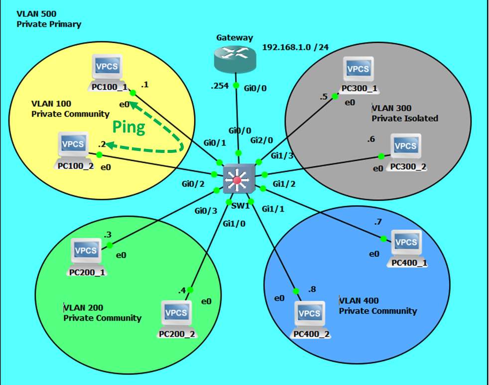
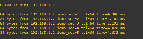
Extra-community VLAN Communication will Fail.
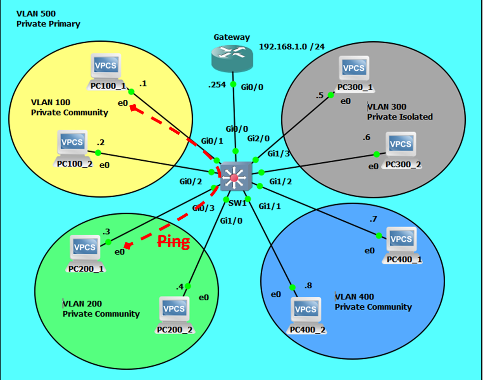

Community-isolated Communications will Fail.
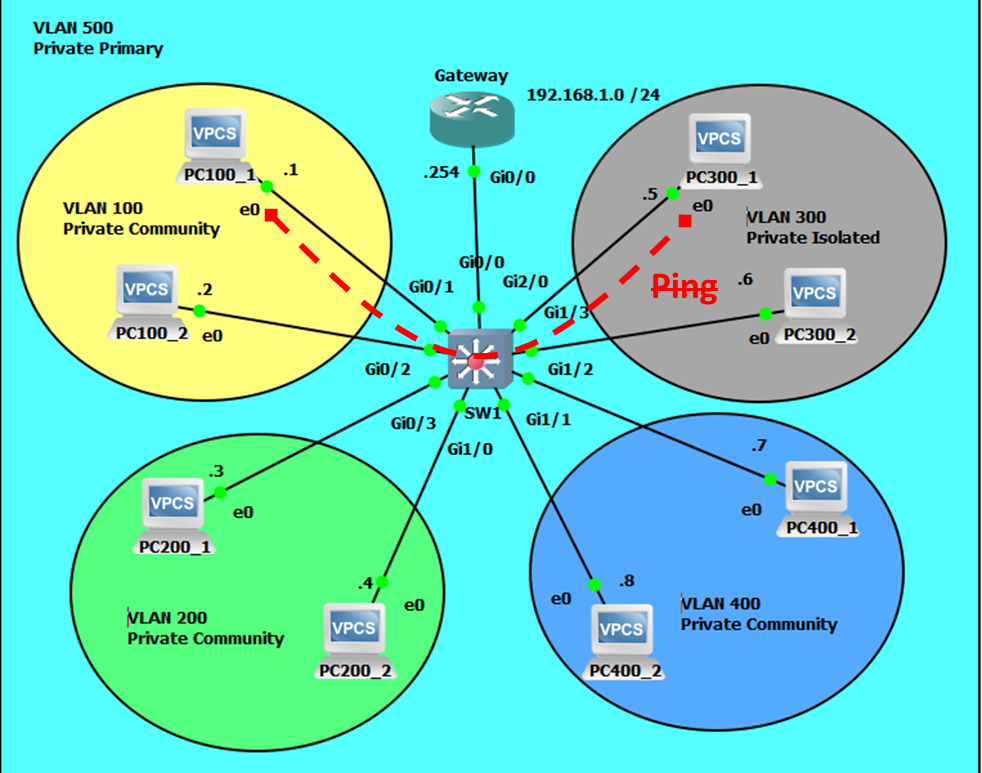

Intra-isolated Communications will Fail.
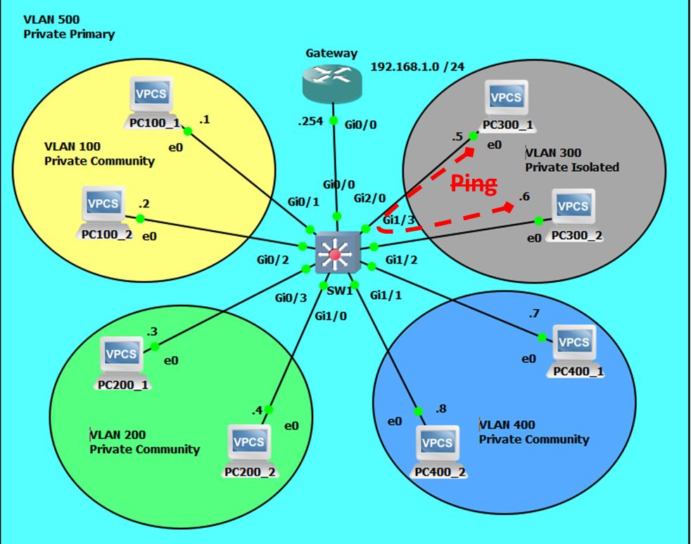

Community-gateway Communicatons will be Successful.
Isolated-gateway Communications will also be Successful.